
Instructions:
1) Be sure to have the correct tools and supplies for for the job. If you do not have them, get them. You will need a regular size Phillips screwdriver, a smaller size Phillips screwdriver, needlenose pliers, wire cutters or other flush cut nippers, a hobby knife such as an X-Acto, scissors, a soldering iron, solder, electrical insulating tape, and a black Sharpie permanent ink marking pen. If you intend to mount the DIN jack on the back panel with the rest of the jacks (highly recommended), you will need to use a chassis punch (a small hand tool that safely cuts a clean hole in a metal panel) to make the hole for the DIN jack, and an electric drill with a 1/8" or similar size drill bit to drill holes for the 4-40 hardware used to mount the DIN jack, and also a 1/4" or 5/16" drill bit to make a pilot hole to start the chassis punch. The correct size for mounting a MIDI DIN jack is 14.5 mm metric or 5/8" SAE (.62"/15.9 mm) in American sizes. A chassis punch may be purchased from any good tool or hardware store. If it is more convenient, a punch may be mail ordered via internet or telephone from Mouser Electronics at http://www.mouser.com or (800) 346-6873. The Mouser part number is 586-3803 for the name-brand Greenlee 730-5/8 (about $30). The cheaper house brand part number is 380-0145 (less than $20). The service from Mouser is unpredictable and the house brand ordered by Synhouse for the test installation took three months to be delivered, while the Greenlee part was delivered in one week. Mouser refused to give even a small discount to customers of Synhouse, so no recommendation is deserved or being made here, and any other source you know of to buy this type of tool is highly recommended and certainly a better place to buy from for all of your needs now and in the future. You will also need an 11 mm wrench (for Greenlee) or 1/2" wrench (for the Mouser house brand punch) or adjustable wrench to turn the chassis punch while cutting the hole. An automatic center punch would also be useful. This is an inexpensive spring-loaded pointed punch that can mark your drilling spot without the use of a hammer. Marking the holes with this small indentation will allow you to drill cleanly without slipping and scratching the synthesizer or drilling through your knee.
2) Fully test the ARP Odyssey to be converted to MIDI. Be sure that all functions such as the envelope generators work and that the instrument plays in tune while playing along with a known well-tuned instrument such as a newer digital synthesizer or sampler keyboard. If it doesn't work properly without MIDI, it certainly won't work with it.
3) Extreme caution should be taken while working on the ARP Odyssey. The unit should be unplugged while open and even then, the power supply may pose some electric shock hazard due to residual voltage in the power supply.
4) Remove the four Phillips screws that hold the top panel in place. Two are on the front right side, two are on the front left side. Lift the lid to the open position, it will swing up on the hinges.
5) Turn the synthesizer upside down and shake out any dust and debris that may have accumulated inside the instrument over the years.
6) Determine the place where the
MIDIJACK circuit board will be mounted and test fit the board into its'
correct place inside the case. Be careful to avoid putting the board
or wires near the high voltage connections in the right rear of the instrument.
Mark the correct mounting holes on the panel with a pencil, marker,
or needle using the paper drilling template provided with the MIDIJACK
hardware packet. A photo called ARP-pic1 shows the paper drilling
template in place:


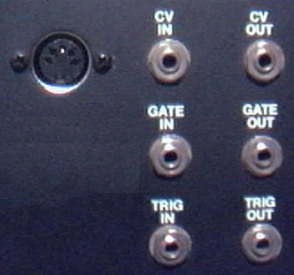
8) Determine the place that the MIDI
input DIN jack will be mounted. A good place to mount it is on the
back panel to the left of the CV IN jack, as photographed in this
example. There is a lot of room on the rear panel of the Odyssey,
so you may mount the DIN jack wherever it suits you best. The way
to make this look like original ARP factory equipment is to mount the DIN
jack inside the metal panel after marking the bare metal edges of the hole
with a black Sharpie permanent ink marking pen to match the black finish
of the original metal chassis. Use the paper template to mark the
correct spots to drill and cut as shown in ARP-pic4:


10) The MIDIJACK #1 black and #2
red wires must be soldered in place to get the ground and power for the
MIDIJACK. There is a ground terminal on each of the 1/8'' jacks which
connects to the sleeve of the jack, and none of them have factory
wires soldered to them because they are grounded directly to the chassis.
Solder the MIDIJACK #1 black wire to any one of the ground terminals,
such as the one shown in ARP-pic8, where the MIDIJACK #1 black wire
can be barely seen in the dark lower left corner:


11) Locate the factory ARP red wire which is soldered to the back of the CV IN jack. Remove the wire from the solder terminal by desoldering it. Solder the MIDIJACK #3 blue wire to the now-empty isolated CV terminal.
12) Solder the MIDIJACK #4 white wire to the now-disconnected factory ARP red wire. Carefully wrap the solder joint with electrical insulating tape.
13) Locate the factory ARP green wire which is soldered to the back of the GATE IN jack. Remove the wire from the solder terminal by desoldering it. Solder the MIDIJACK #5 yellow wire to the now-empty isolated gate terminal.
14) Solder the MIDIJACK #6 green wire to the now-disconnected factory ARP green wire. Carefully wrap the solder joint with electrical insulating tape.
15) Photo ARP-pic8 shows the inside
of the rear of the jackpanel with the DIN jack mounted and the MIDIJACK
wires already connected to the proper points. A look at this will
give some idea of what it will look like when done correctly:
17) The MIDIJACK hardware packet contains nylon cable ties which should be used to tie the MIDIJACK wires into little bundles and to attach them to the factory wires inside the Odyssey now that all connections have been made. This will secure the MIDIJACK wires to the inside of the chassis so they will not rattle and break loose inside the case once the instrument is returned to service.
18) Carefully examine all soldered connections for possible short circuits before closing the instrument.
19) Close the instrument and secure it with the four Phillips screws.
20) Test and calibrate using the procedures described in the Original MIDIJACK Quick Installation Manual.
21) This installation can be completed in 30 minutes.
Performance Tips:
The ARP Odyssey
has a trigger circuit separate from the gate circuit to provide multiple
note envelope triggering. This is not required for MIDI operation
because the Original MIDIJACK has special software to do multiple note
triggering like an ARP or single note triggering like a Moog. The
user can select either mode at any time. For this reason, the
local keyboard will still trigger the envelope generator even with the
MIDI activated. It is impossible to bypass the keyboard triggering
completely so it is probably a good idea not to play the local Odyssey
keyboard while MIDI is in use or vice versa.
Copyright © 1/3/2001 Synhouse Multimedia
Corporation