The following plans
describe a method of
adding MIDI capability to the
Roland SH-09 analog synthesizer with the Synhouse Original MIDIJACK.
The SH-09
is especially well suited for this modification due to the tiny size of
the MIDIJACK circuit board. You may be able to do this yourself if
you have experience with electronic repair and the soldering of wires
and
circuit boards. If not, you can ship
the unit to Synhouse L.A. for a quick, low cost Factory
Installation.
For
self-installation, it is best to
print these notes out on paper
to look at while working on the instrument and make notes and check off
the steps as you go. As with any project, it is best to completely
read and understand each step of the instructions before starting. The
particular installation on which this document is based was on Roland
SH-09 serial #044691, other revisions may be different.
All
repairs and modifications made to your instruments will be done at your
own risk and Synhouse Multimedia Corporation assumes no liability for
personal
injury caused or damage to equipment or loss of use caused directly or
indirectly by the use of these plans. If in doubt, don't do
it!
Instructions:
1) Be sure to have
the correct tools and
supplies for for the
job. If you do not have them, get them. You will need
a regular size Phillips screwdriver, a smaller size Phillips
screwdriver, needlenose pliers, strong wire cutters or other flush cut
nippers, a hobby knife such as an X-Acto, scissors, a soldering iron,
solder, and electrical insulating tape. A Dremel Moto-Tool
or hot knife will be useful if you wish to carve out the inner portion
of the left side plastic end cap to accommodate the MIDIJACK board, as
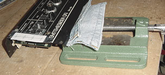
shown in this example by Synhouse. If you intend to mount the
DIN jack on the back panel with the rest of the jacks, you will need
to use a chassis punch (a small hand tool that safely cuts a clean hole
in a metal panel) or step drill (a cone-shaped drill bit with many
steps on it from small to large) to make the hole for the DIN jack, and
an electric
drill with a 1/8" or similar size drill bit to drill holes for the 4-40
hardware used to mount the DIN jack, and also a 1/4" or 5/16" drill
bit to make a pilot hole to start the chassis punch. The correct
size for mounting a MIDI DIN jack is 14.5 mm metric or 5/8" SAE
(.62"/15.9
mm) in American sizes. A chassis punch may be purchased from any
good tool or hardware store. If it is more convenient, a punch
may be mail ordered via internet or telephone from Mouser Electronics
at
http://www.mouser.com or (800)
346-6873. The Mouser part number is 586-3803 for the name-brand
Greenlee 730-5/8
(about $30). The cheaper house brand part number is 380-0145 (less
than $20). You will also need an 11 mm wrench (for Greenlee) or 1/2"
wrench (for the
Mouser house brand punch) or adjustable wrench to turn the chassis
punch
while cutting the hole. An automatic center punch would also be useful.
This is an inexpensive spring-loaded pointed punch that can mark your
drilling
spot without the use of a hammer. Marking the holes with this small
indentation will allow you to drill cleanly without slipping and
scratching
the synthesizer or drilling through your knee.
Always wear eye
protection
such as safety glasses when working with power tools, cutting tools, or
punching tools.
The board and DIN
jack can be mounted in the metal
as shown in this example done by Synhouse, which requires a drill
and a chassis punch, or the entire assembly can be done in the plastic
end caps using only a hobby knife, with no drill or chassis punch
required.
2) Fully test the
Roland SH-09 to be
converted to MIDI. Be sure that all functions such as VCF envelope work
and that the instrument
plays in tune while playing along with a known well-tuned instrument
such
as a newer digital synthesizer or sampler keyboard. If it doesn't
work properly without MIDI, it certainly won't work with it.
3) The installation
of the MIDIJACK in a
Roland SH-09 is fairly
simple, as long as you follow these instructions closely. All
of the electronic work can be done on two boards without removing them.
The Roland SH-09 has jacks soldered directly into the PC board and the
safest way to access the signals without compromising the strength of
the
factory solder joints is to leave them just as they are and cut a tiny
notch in the copper circuit trace a short distance away from the jack
itself. This modification reroutes the local keyboard signals through
the computer-controlled
analog switching matrix of the MIDIJACK by extracting the signal and
inserting
the users' choice of local keyboard control or MIDI.
4) Extreme caution
should be taken while
working on the Roland
SH-09. The unit should be unplugged while open and even then, the power
supply may pose some electric shock hazard due to residual voltage
in the power supply.
5) The entire
synthesizer and interface
jacks are mounted on three
boards which are bolted like a PC board sandwich to the underside of
the
slider control panel. To make your life easier and do the installation
quickly, completely remove this assembly as one unit. Remove
the three Phillips screws on the lower edge of the rear side, and
remove the three Phillips screws on each end of the control panel that
are holding it onto the plastic end caps. They are on the bottom
panel, two on the right edge, two on the left.
6) Open the case
slightly and locate the
green wire that serves
as a ground strap, which ends in a terminal attached by a screw to
the rear right corner of the base. Remove this screw to release the
wire. Slightly separate the two halves of the instrument, which
will still be connected by wires. Turn the synthesizer upside down
and shake out any dust and debris that may have accumulated inside the
instrument over the years. If required, the two plastic end
caps may be removed by removing three Phillips screws on each end of
the
underside of the base, and note that each one has an extra screw
to be removed approximately one inch in from the others. Remove
anything
else that may be holding the end caps in place. This should be done
with extreme caution, as the the end caps are very fragile and possibly
already broken.
7) Before unplugging
any wires, look at
them very carefully, and note their positions before removing any of
them. There is a
power supply in the base of the instrument that provides ground via two
bundles of black wires and supplies a regulated +/-15 volts DC. There
are two bundles of red wires that provide +15v, and two bundles of
blue wires that provide -15v. BEWARE
OF THE CONNECTOR POLARITY! At
first glance, it may appear that there are a series of identical
3-pin connectors that supply +/-15v to various modules of the
synthesizer. This is NOT the case. Some are wired backwards, and
reconnecting
them the wrong way would certainly destroy some of the circuits. A good
way to mark them is to use a marking pen such as a Sharpie to make
a random slash mark or two or three across both halves of the
connectors, a little differently on each, so that you can see if they
are reconnected
properly later on.
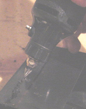
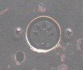
8) The wires with white connectors have a snap lock holding them in place. To release the lock, insert a small screwdriver and pry it open as shown in SH-09-pic1:
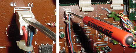
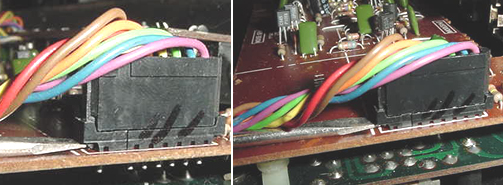
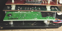
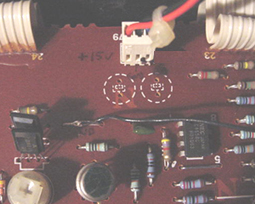
9) The wires on the end are held in place by a black connector which has a snap lock holding it in place. To release the lock, press the tabs inward with the screwdriver as shown in SH-09-pic2:
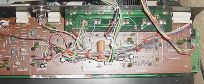
10) The upper
panel/synth assembly
should be free of the base
now. All electronic work can be done by connecting the MIDIJACK wires
to the main board and jack board.
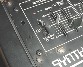
11) For this
demonstration unit done by
Synhouse, considerable
effort was made to keep all MIDIJACK controls on the synth control
panel, visible at all times, in a way that would look the most like
something
done at the factory. This meant putting the MIDIJACK board at the
far left of the control panel, just to the left of the MODULATOR
section, and the DIN jack on the rear panel, just to the right
of the D in ROLAND. This required three special accommodations to
be made. The left end cap of the SH-09 was hollowed out inside to
allow space for the MIDIJACK board, and the rear of the board was
insulated with electrical tape to prevent a short circuit against the
metal
frame right next to it. The main synth board was temporarily lifted
an inch out of place to make room for the chassis punch and wrench
while
cutting the hole for the DIN jack.
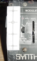
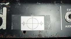
12) Determine the place where the MIDIJACK circuit board will be mounted and test fit the board into its' correct place inside the case. The easiest place would be on the underside or in the plastic end caps, which would not require a drill or chassis punch. Mark the correct mounting holes on the front panel with a pencil, marker, or needle using the paper drilling template provided with the MIDIJACK hardware packet as seen in this photo called SH-09-pic3 which shows the paper drilling template taped in place:
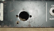
Drill the holes. A photo called SH-09-pic5 shows the location of the newly drilled mounting holes:
13) Mount the MIDIJACK board in place. When mounting the MIDIJACK board, the switch should be fitted so well in the panel that the switch stem will not wiggle at all once in place. It should not have any free play but also should not be so tight that it binds. When the switch is pressed, it should have a definitive "click" and bounce back like the button on a new VCR. You will never regret spending too much time on this and good attention to detail will make the perfect MIDIJACK installation. The hole in the panel that is over the MIDIJACK scale adjust trimpot should be large enough so a Synhouse Pocket Screwdriver can fit through the panel for periodic adjustment. The perfect MIDI control panel installation is shown in SH-09-pic6:
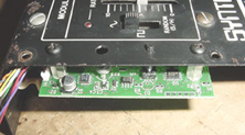
Photo SH-09-pic7 shows the underside and the insulating tape applied to it to prevent shorting in this tight space:
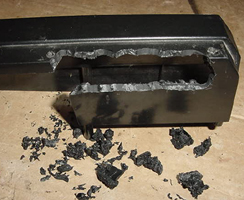
If the board is installed in this manner, a Dremel Moto-Tool can be used to carve out the inside of the left end cap to allow space for it, as shown in SH-09-pic8:
Always wear eye protection such as safety glasses when working with power tools, cutting tools, or punching tools. When finished, it should look something like the one shown in SH-09-pic9:
14) Determine the
place that the MIDI
input DIN jack will be mounted. In this example, it was mounted on the
rear panel, just to
the right of the D in ROLAND. To do this, the main synth board
was temporarily lifted an inch out of place to make room for the
chassis
punch and wrench while cutting the hole for the DIN jack. The PC
board is held in place by snap lock nylon standoffs that can be
released
by pinching the ends with needlenose pliers. To avoid this extra
work, the DIN jack could be mounted anywhere else on the instrument.
Use the paper template to mark the correct spots to drill and cut as
shown
in SH-09-pic10:
If mounting in metal,
it is advisable to
use a chassis punch to
make the hole for the DIN jack. Remember that the DIN jack is to
be mounted with the smaller 4-40 hardware size rather than the larger
6-32
size that secures the main board. Drill two holes for the screws
then drill a slightly larger hole in the center to act as a pilot hole
for the chassis punch. Use the chassis punch to cut the hole and
be sure that the wrench is turning the tool from inside the synth, not
outside, so the cutting edge is coming from the outside. This will
ensure that the outer edge is perfectly smooth. The properly
cut mounting holes may be seen in SH-09-pic11:
15) The MIDIJACK #1
black and #2 red
wires must be soldered in
place to get the ground and power for the MIDIJACK. Examine the center
sections of the synth board closely. There is a wire jumper with
the proper ground, located one inch from the +15v power pin marked
"79". Solder the MIDIJACK #1 black wire to this point as shown in
SH-09-pic13:
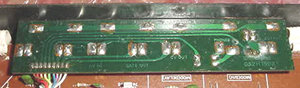
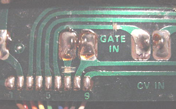
16) Examine the jack
board PCB with the
CV/gate jacks on it. All MIDIJACK I/O connections can be made on this
jack board. It can
best be done without removing it. Leaving it bolted in place, you must
cut two PCB traces and solder four wires in place, one on
each side of each cut trace. Before modification, the jack
board is as shown in SH-09-pic15:
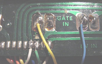
17) Carefully examine
all cuts and
connections made to the jack
board for mistakes or possible short circuits. Make sure that there
are no foil pieces or solder bits left hanging around to cause a short
circuit later on. The CV and gate terminals are now isolated and
routed through the MIDIJACK.
18) The MIDIJACK #7
brown wire and #8
violet wire (unless it is
used for a special function as described in the Advanced Installation
Manual)
are not required for adding MIDI to the Roland SH-09, but it is a
good idea not to permanently cut these wires off, as an alternate
installation method may become useful later. It is best to wrap the
ends of these unused wires with heat shrink tubing or electrical
insulating
tape and bundle them with the other wires.
19) Use the small
cable ties provided
with the MIDIJACK to bundle
the excess wires and hold them in place as shown in SH-09-pic18:
21) It is time to
reassemble the Roland
SH-09 as it was before. Be sure to properly reconnect each connector
that was removed, then
put the pieces back together with the screws, and close the chassis
halves and secure with screws on the upper and lower sides. As done
by Synhouse, the new MIDI control panel appeared as shown in
SH-09-pic19: