 |
Roland SH-1 |
|
Roland SH-1 |
|
FREE plans to add MIDI capability to the rare Roland SH-1 with the Synhouse MIDIJACK! |
 |
The following plans describe a method of adding MIDI capability to the
Roland SH-1 analog synthesizer with the Synhouse MIDIJACK. The SH-1
is especially well suited for this modification due to the tiny size of
the MIDIJACK circuit board and the retro chrome look of the DIN jack.
No drilling is required. There is a empty place on the SH-1 jackpanel
that is perfect for the installation. In addition, the micro
size and black color of the MIDI button are such a perfect match for the
SH-1 that it makes it look as if it came from the factory with the MIDI
interface. You can do this yourself if you have a little experience
with electronic repair and the soldering of wires and circuit boards.
If not, these plans may assist a professional repair shop installing
the MIDIJACK for you. It is best to download these notes and photos
and print them out on paper to look at while working on the instrument
and make notes and check off the steps as you go. As with any project,
it is best to completely read and understand each step of the instructions
before starting. All repairs and modifications made to your instruments
will be done at your own risk and Synhouse Multimedia Corporation assumes
no liability for personal injury caused or damage to equipment or loss
of use caused directly or indirectly by the use of these plans. If
in doubt, don't do it!
Instructions:
1) Be sure to have the correct tools and supplies for for the job. If you do not have them, get them. You will need a regular size Phillips screwdriver, a smaller size Phillips screwdriver, a wrench for the 1/4" jack nuts, needlenose pliers, strong wire cutters or other flush cut nippers, a hobby knife such as an X-Acto, scissors, a soldering iron, solder, and electrical insulating tape. You will not use a drill for this installation under any circumstances.
2) Fully test the Roland SH-1 to be converted to MIDI. Be sure that all functions such as VCF envelope work and that the instrument plays in tune while playing along with a known well-tuned instrument such as a newer digital synthesizer or sampler keyboard. If it doesn't work properly without MIDI, it certainly won't work with it.
3) The installation of the MIDIJACK in a Roland SH-1 is slightly more complicated than it is with most American synthesizers because the installer must remove three of the Roland circuit boards and cut two copper traces to isolate and access the correct analog I/O signals. Many older American synthesizers have panel-mounted CV/gate jacks with solder terminals and the MIDIJACK wires can simply be soldered right at the inside of the panel and the whole MIDI conversion job can be done in 20 minutes. The Roland SH-1 has jacks soldered directly into the PC board and the safest way to access the signals without compromising the strength of the factory solder joints is to leave them just as they are and cut a tiny notch in the copper circuit trace a short distance away from the jack itself. This modification reroutes the local keyboard signals through the computer-controlled analog switching matrix of the MIDIJACK by extracting the signal and inserting the users' choice of local keyboard control or MIDI.
4) Extreme caution should be taken while working on the Roland SH-1. The unit should be unplugged while open and even then, the power supply may pose some electric shock hazard due to residual voltage in the power supply.
5) Remove the four Phillips screws that hold the upper and lower case halves together. They are on the bottom panel, two on the right edge, two on the left.
6) Open the case on and turn the synthesizer upside down and shake out any dust and debris that may have accumulated inside the instrument over the years.
7) Only a slight disassembly will be required so close the lid and remove the tuning, volume, and portamento knobs by pulling upward while taking care not to lose the soft clear plastic inserts that are underneath. Remove the plastic caps from the from the bender VCO/VCF sensitivity sliders.
8) Remove the two screws holding the bender in place.
9) Using a socket wrench, combination wrench, or adjustable wrench, remove the 8 nuts and washers from the 1/4" analog jacks on the jackpanel at the rear of the instrument. Do not use pliers for this. Roland chooses to make musical instruments out of soft plastic and once scratched, they can never be fixed.
10) Open the case and
remove the two circuit boards at the left. The first and smallest
one is held in place by nylon PC board standoffs that can be pinched with
pliers to snap off. The second PCB must be unscrewed from the plastic
chassis. The two boards will still be held together by numerous wires.
11) Determine the
place where the MIDIJACK circuit board will be mounted test fit the board
into its' correct place inside the case. The best place to mount
the MIDIJACK board is on the panel near the performance controls,
between the volume knob and transpose switch. Notice that there are
two plastic support posts inside the case obstructing the mounting of the
MIDIJACK board but do not remove them yet. Mark the correct mounting
holes on the front panel with a pencil, marker, or needle using
the paper drilling template provided with the MIDIJACK Installation Manual.
Do not use a drill. The panel of the SH-1 is made of soft plastic
and a drill, even on its' slowest speed, will build up friction,
generate heat, and burn the plastic permanently. Use a standard
X-Acto knife blade with the sharp point and twist it in place until it
starts to dig a little hole. When it gets close to reaching the other
side, you can look inside and see the tip coming through and dig
back from the inside as well. A perfectly round hole can be shaped
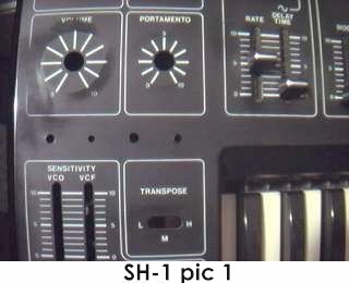
using this technique. See the photo called SH-1 pic 1 which
shows the perfect panel holes.
12) Try to mount the
MIDIJACK board in place and see the two plastic support posts that are
in the way and cut them out carefully with strong wire cutters or similar
flush cut nippers. It is just soft plastic so take much care not
to twist them as they are removed. Cut them out, do not pull
them out. If they do not fall out by their own weight, you
are pulling too hard. These supports will no longer be needed and
the two screws that were in them may be used for other purposes.
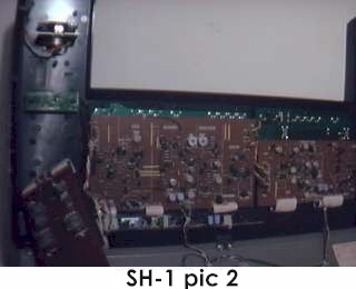
Nibble away at the nubs until the interior plastic surface is nice and
flush. Photo SH-1 pic 2 shows the MIDIJACK board mounted in
place with the two left SH-1 boards removed for installation. Mount
the MIDIJACK in place without fully tightening the screws and try
to get the perfect size holes by twisting the X-Acto knife but do not make
them too big. The switch should be fitted so well in the panel that
the switch stem will not wiggle at all once in place. It should not
have any free play but also should not be so tight that it binds.
When the switch is pressed, it should have a definitive "click" and
bounce back like the button on a new VCR. You will never regret spending
too much time on this and good attention to detail will make the perfect
MIDIJACK installation. The hole in the panel that is over the MIDIJACK
scale adjust trimpot should be enlarged so a Synhouse Pocket Screwdriver
can fit through the panel for periodic adjustment. The screws that
secure the MIDIJACK board in place should be tightened very carefully.
Do not overtighten the screws. They are solid steel and the SH-1
is the cheapest, softest plastic. You will never regret not
cracking the case of your SH-1. Such an installation will be nearly
invisible, yet put the MIDI function button at the players' fingertips.
True story: The first SH-1 synthesizer ever converted to MIDI with
a Synhouse MIDIJACK was done by a professional Synhouse Analog Tech and
when the owner of the synthesizer first saw it, it took him 30 seconds
to find the MIDI button that was right in the middle of the control panel.
For the serious Analog User and synthesizer collector, an ultra-clean
installation pays off.
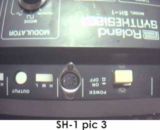
13) Determine the
place that the MIDI input DIN jack will be mounted. The perfect place
is on the rear jackpanel in the blank spot between the power switch and
the audio output jack. See photo called SH-1 pic 3.
The way to make this look like original Roland factory equipment is to
mount the DIN jack outside the plastic panel instead of inside the panel
as in a normal MIDIJACK installation. To do this, mark one
of the two wires (#9 orange or #10 gray) at the terminals of the DIN jack
with a marking pen or tape to remember the polarity then desolder both
wires. There is too little room to properly use the paper template
so turn the DIN jack upside down and use it as its own template.
Do not use a chassis punch or drill to make the hole for the DIN jack.
Be absolutely certain that the jack is dead-centered, then proceed
with cutting the two holes for the screws with the tip of the X-Acto
knife, remembering that the DIN jack is to be mounted with the smaller
4-40 hardware size rather than the larger 6-32 size that secures the main
board. The MIDIJACK hardware packet contains both long and short
4-40 screws for the DIN jack. Use the two long ones. The holes
should be barely large enough to fit the screws into and hold the DIN jack
(still upside down) completely straight. A hole should then be cut
right in the center between the two as a pilot hole for what will be the
biggest hole of the three. The center hole should be carefully carved
out with an X-Acto knife, preferably from the inside of the case
so that if you slip and scratch, no one will see. When all
three holes are perfect, put the DIN jack in place with the two screws
from the outside, and the two split washers and 4-40 nuts on the
inside against the plastic and tighten with a small Phillips screwdriver
from the outside and the needlenose pliers from the inside. These
should be fairly tight as they are going onto the metal surface of the
DIN jack. If done cleanly and correctly, the SH-1 will look
like it had MIDI when it came from the factory. It is best to leave
the wires to the DIN jack disconnected at this time.
14) The black and
red wires must be soldered in place to get the ground and power for the
MIDIJACK, but it is best to leave them unsoldered at this time.
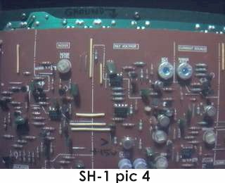
See the photo called SH-1 pic 4 which shows the best place to obtain
the proper ground and power. The #1 black wire should be cut to the
proper length to reach the ground plane. It is best to connect to
the solder bump beneath the "G" of the word "ground" as shown in the photo,
well clear of the screw holding the PCB in place. The #2 red wire
should be cut to the proper length to reach the regulated +15v jumper as
shown in the photo with the arrow pointing to it. An ultra-clean
installer may prefer to cut all wires to the perfect length as described
here, but other users may prefer to save time by using the precut,
stripped, and tinned wires at their standard lengths and there is
no electrical reason not to. It is just a matter of preference and
after the job is done and the SH-1 is put back into service, who
will care?
15) Remove the circuit
board which contains 8 analog jacks by unplugging the 9-pin connector and
power connector and pulling it out of the instrument entirely. This
is the PCB that will require rework and extra connections to make the MIDIJACK
work. It is a good idea to make a mark with a marking pen anywhere
across the joint of a mating connector before disconnecting. The
unique mark will allow future reconnection in a way that will visibly show
whether or not it is the correct connector on the correct mating header
with the correct polarity.
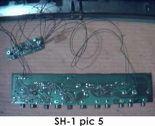
16) Placing the SH-1
jackboard on a suitable work surface, locate the proper cutting and
soldering points. Two traces will be cut and four MIDIJACK wires
will be soldered to the bottom foil side of this board. Photo SH-1 pic
5 shows the jackboard with the MIDIJACK board already connected to
the proper points. A look at this will give some idea of what it
will look like when done correctly. The jackboard should be placed
foil side up on the work surface with the upside down jacks pointing toward
you, the same position shown in the photo.
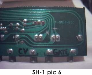
17) SH-1 pic 6
shows the two copper foil circuit board traces to be cut. They are
the traces coming from the tip of the 1/4" plugs inserted into the CV/gate
input jacks, and they also carry the local SH-1 keyboard signal from the
switched input to the jack. Carefully cut the traces with an X-Acto
knife by digging a nice, even groove to break the signal. Make sure
that there are no foil pieces left hanging around to cause a short circuit
later on. The CV and gate terminals are now isolated and a new wire
can be soldered onto each of the terminals that have been isolated.
Refer again to SH-1 pic 5.
18) Solder the MIDIJACK
#3 blue wire to the newly isolated CV terminal.
19) Solder the MIDIJACK #5 yellow wire to the newly isolated gate terminal.
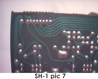
20) The upper left of the jackboard will have the end of 9 pins coming through from the other side, as seen in SH-1 pic 7. Locate these pins. A number 9 will be seen upside down at the right when the board is in the correct position, directly above pin 9. The remaining pins are numbered from right to left: 8, 7, 6, 5, 4, 3, 2, 1.
21) Solder the MIDIJACK #4 white wire to pin 4.
22) Solder the MIDIJACK #6 green wire to pin 7.
23) Carefully examine all cuts and connections made to the jackboard for possible short circuits before remounting in the rear jackpanel.
24) Remount the jackboard in the rear jackpanel.
25) If everything looks good and well-routed, proceed with soldering MIDIJACK wires #1 black and #2 red at connect points described in step 14 above.
26) Trim MIDIJACK wires #9 orange and #10 gray to a suitable length as desired and resolder to the correct pins on the DIN jack.
27) It is probably best not to use the small cable ties to hold the wires in this particular installation. Instead, cut short pieces of electrical insulating tape and use them to secure the MIDIJACK wires to the edges of the nearest circuit boards so they will not rattle and break loose inside the case once the instrument is returned to service.
28) Carefully examine
all connections and leads for possible short circuits before reassembling
chassis.
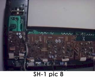
29) Reinstall bender,
the two left side circuit boards, knobs, and slider caps.
Photo SH-1 pic 8 shows the two SH-1 boards reinstalled, hiding
the new MIDIJACK board from view.
30) Close chassis and secure with four screws on the bottom side.
31) Test and calibrate using the procedures described in the MIDIJACK Installation Manual.
32) This installation can be completed in 40-60 minutes. Extra time spent making a perfect installation is time well spent.
33) The KYBD/EXT CV GATE switch should always be in the EXT CV GATE position whether using the local SH-1 keyboard, CV/gate, or MIDI for control. The MIDIJACK MIDI button will activate or deactivate MIDI operation. It is impossible to bypass the keyboard completely so do not play the local SH-1 keyboard while MIDI is in use or vice versa.
Copyright © 2000 Synhouse
Multimedia Corporation