 |
Roland SH-101 |
|
Roland SH-101 |
|
FREE plans to add MIDI
capability to the
|
 |
The following plans describe a method of adding MIDI capability to the
popular Roland SH-101 analog synthesizer with the Synhouse MIDIJACK.
The SH-101 is especially well suited for this modification due to the tiny
size of the MIDIJACK circuit board and the fact that it is the first analog
MIDI retrofit ever made that costs less than the instrument itself!
There is plenty of space on the SH-101 to mount the MIDIJACK with the provided
hardware. The original factory portamento will still work with MIDI.
This modification reroutes the local keyboard signals through the computer-controlled
analog switching matrix of the MIDIJACK by extracting the signal and inserting
the users' choice of local keyboard control or MIDI. You can do this
yourself if you have a little experience with electronic repair and the
soldering of wires and circuit boards. If not, these plans
may assist a professional repair shop installing the MIDIJACK for you.
It is best to download these notes and photos and print them out on paper
to look at while working on the instrument and make notes and check off
the steps as you go. As with any project, it is best to completely
read and understand each step of the instructions before starting.
The particular installation on which this document is based was on Roland
SH-101 serial #342185, other revisions may be different. All
repairs and modifications made to your instruments will be done at your
own risk and Synhouse Multimedia Corporation assumes no liability for personal
injury caused or damage to equipment or loss of use caused directly or
indirectly by the use of these plans. If in doubt, don't do
it!
Instructions:
1) Be sure to have the correct tools and supplies for for the job. If you do not have them, get them. You will need a regular size Phillips screwdriver, a smaller size Phillips screwdriver, needlenose pliers, wire cutters or other flush cut nippers, a hobby knife such as an X-Acto, scissors, a soldering iron, solder, electrical insulating tape, and a black Sharpie permanent ink marking pen.
2) Fully test the Roland SH-101 to be converted to MIDI. Be sure that all functions such as the envelope generator work and that the instrument plays in tune while playing along with a known well-tuned instrument such as a newer digital synthesizer or sampler keyboard. If it doesn't work properly without MIDI, it certainly won't work with it.
3) The installation of the MIDIJACK in a Roland SH-101 is slightly more involved than it is with most other synthesizers because the installer must replace the original Roland AC adapter power supply with a different type and use a slightly different internal power connection method. Additionally, the installer must cut two copper traces to isolate and access the correct analog I/O signals. Many older American synthesizers have panel-mounted CV/gate jacks with solder terminals and the MIDIJACK wires can simply be soldered right at the inside of the panel and the whole MIDI conversion job can be done in 20 minutes. The Roland SH-101 has jacks soldered directly into the PC board and the safest way to access the signals without compromising the strength of the factory solder joints is to leave them just as they are and cut a tiny notch in the copper circuit trace a short distance away from the jack itself. This modification reroutes the local keyboard signals through the computer-controlled analog switching matrix of the MIDIJACK by extracting the signal and inserting the users' choice of local keyboard control or MIDI.
4) Remove the 12 small black Phillips screws that hold the lower case cover in place. They are on the bottom panel. Remove the cover.
5) Turn the synthesizer upside down and shake out any dust and debris that may have accumulated inside the instrument over the years.
6) Only a slight disassembly will be required so place the instrument on a soft surface with the keys downward and the exposed circuitry facing upward. This will be your general work position for the required electronic work.
7) Obtain a new power supply to use the SH-101 with MIDI. The original BOSS PSA Roland AC adapter 12449543 has an output voltage that is too low for the MIDIJACK. The MIDIJACK must have at least +12 volts DC input to allow it to be stabile and put out the top MIDI note 127 which is +10.58 volts. The original Roland unit was said to be +9 volts DC @ 500mA, but when measured under load it was found to be +11.53 volts and dropped after some time. The SH-101 uses an old but clever powering method which allows portable operation with 6 "C" cells, which comes out to only +9 volts total if the batteries are good. When an AC adapter is plugged in, the DC IN jack switches out the connection between the batteries and the synthesizer circuitry. If this AC adapter provides only +9 volts, that is fine, or if the AC adapter provides +17 actual volts that is okay as well.
The SH-101 has a DC-DC converter
that steps up the voltage to about +20 volts unregulated, then runs
it through a linear voltage regulator that puts out the regulated +15 volts
that the analog synthesizer circuitry runs on. To check and see how
it is working, both before and after you replace the original power
supply, there are three test points to measure the voltage:
If you would like to test for proper operation once you are inside the instrument, you can:
a) Check the unregulated input voltage at the red wire directly behind the DC IN jack on the SH-101. With the synthesizer turned on, this will show you the voltage under a real load.
b) Next you can test the stepped-up voltage at the cathode end (the end with the little black band) of diode D1 which is on the far left end of the main circuit board near the MODULATION GRIP jackboard. This was found to be +21 volts.
c) The next point to
check is the regulated +15 volt supply which can be found on IC 13 pin
16, which is a Curtis Electromusic CEM 3340 VCO chip. It was
found to be +14.87 volts.
The standard MIDIJACK installation
connects to the regulated synth supply, usually +12 or +15 volts,
but in this case, it was found that the SH-101 was not designed to
provide the extra 35mA required by the MIDIJACK. The voltage on the
+15 volt supply begins to drop as soon as the MIDIJACK is connected,
a sure sign that it will overload the SH-101 and cause damage. This
is no problem, because the MIDIJACK has a power supply that has better
line and load regulation than the SH-101 anyway, and can operate
on a much lower voltage than the +21 volts going into the SH-101 regulator.
For this reason, we will draw the power for our new MIDI system from
the unregulated DC IN jack. The original unregulated power voltage
is too low, so we will use a new power supply. You must use
a power supply which is at least +12 volts DC when loaded (connected to
the running synthesizer), and a little more is better. A +14
VDC or +15 VDC power supply with a current rating of 300mA or higher is
best. This must have a co-ax type of power connector with an inside
diameter of 2.1 mm. The center must be -negative and the outside
+positive. This is not the best way to wire a power connector because
if it is dropped on a grounded metal surface the outside will touch and
short circuit into the ground, but that is the way Roland did it
on the SH-101. Most sensible power supplies you will be able to find
will be wired in the opposite polarity, but it is easy to cut the
connector off and reverse the polarity for use with the SH-101. Be
careful to insulate the wires after resoldering. This is such a common
type of part that you may already have one in your junk box, but
in the USA, a good and friendly source for this part is Jameco Electronics
at http://www.jameco.com or (800) 831-4242. The Jameco catalog number
is 129314. It is a +14VDC@360mA AC adapter which costs $4.95,
but they have many more that will work just as well. The power supply
used by Synhouse for this installation was catalog number DCTX-1436 for
$3.50 bought from All Electronics at http://www.allelectronics.com or (800)
826-5432. They are an equally friendly source of electronic supplies,
but their stock changes daily, and the +14VDC@360mA supply purchased
and used here may no longer be available, but they have many more
that may work just as well. When this one was used by Synhouse,
the actual voltage when loaded was +16.6 volts and the SH-101 actually
drew less than 100mA. Obtain the correct power supply, wire
it with the correct power plug with the correct polarity, and test
it with your SH-101 before installing the MIDIJACK. Be sure to remove
the batteries from the SH-101. It will no longer be operated on battery
power. Your new power supply will cost less than one set of alkaline
batteries and, unlike the batteries, this new power supply
will most likely last forever.
8) Determine the place
where the MIDIJACK circuit board will be mounted and test fit the board
into its' correct place inside the case. The best place to mount
the MIDIJACK board is probably on the small ledge to the right of the keys,
as photographed in this installation example done by Synhouse. Other
possible places would be on the control panel above the ADSR sliders between
the legends that say VCA and ENV, or on the ends of the instrument.
This spot suggested is a very tight fit and much care must be taken to
get the holes drilled in precisely the right places. There is literally
is not two spare millimeters of space on the sides of the board.
It is a factory fit. Unlike ordinary MIDIJACK installations which
are drilled from the outside, the holes must be marked and drilled
from the inside to be sure the board is centered in the tight space available.
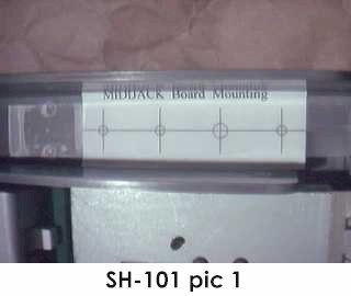
The MIDIJACK hardware packet has paper drilling templates for easy installation.
Use the paper drilling template labeled MIDIJACK Board Mounting to properly
mark and drill the holes. The photo called SH-101 pic 1 shows
the paper drilling template in place. Once carefully taped in place,
the holes may simply be drilled through the paper. Do not use a high-speed
drill. The panel of the SH-101 is made of soft plastic and a high-speed
drill will build up friction, generate heat, and burn the plastic
permanently. Drill at the slowest speed available. The perfect
size drill bit for the switch stem and two screw holes is 9/64",
and the perfect size for the scale adjust trimpot is 3/16". Drill
the holes. If your drill is not slow enough to safely drill plastic,
you can use an X-Acto knife to make the holes by twisting. This is
a little more time-consuming, but works well if you don't have a
drill to use. You can use a standard X-Acto knife blade with the
sharp point and twist it in place until it starts to dig a little hole.
When it gets close to reaching the other side, you can look outside
and see the tip coming through and dig back from the outside as well.
A perfectly round hole can be shaped using this technique.
| 9) Temporarily mount the MIDIJACK board in place. When mounting the MIDIJACK board, the switch should be fitted so well in the panel that the switch stem will not wiggle at all once in place. It should not have any free play but also should not be so tight that it binds. When the switch is pressed, it should have a definitive "click" and bounce back like the button on a new VCR. You will never regret spending too much time on this and good attention to detail will make the perfect MIDIJACK installation. The hole in the panel that is over the MIDIJACK scale adjust trimpot should be approximately 3/16" so a Synhouse Pocket Screwdriver can fit through the panel for periodic adjustment. Once the fitting is correct, permanently mount the board, taking care not to crack the plastic by overtightening the screws. The photo called SH-101 pic 2 shows the completed MIDI control panel. |  |
 |
10) Determine the place that the MIDI input DIN jack will be mounted. The best place is probably on the right side near the rear of the instrument, very near the audio output jack, as shown in this example. The best way to mount this and make it look like Roland factory equipment is to mount the DIN jack outside the plastic panel instead of inside the panel as in a normal MIDIJACK installation. This will also cover the jagged edges left by hand-tooling the hole in the chassis. To do this, mark one of the two wires (#9 orange or #10 gray) at the terminals of the DIN jack with a marking pen or tape to remember the polarity then desolder both wires. Do not use a chassis punch to make the hole for the DIN jack because it will crack the plastic. Use the paper drilling template labeled DIN Jack Mounting to properly mark and drill the holes as shown in SH-101 pic 3. Remember that the DIN jack is to be mounted with the smaller 4-40 hardware size rather than the larger 6-32 size that secures the main board. The MIDIJACK hardware packet contains both long and short 4-40 screws for the DIN jack. Use the two long ones for installation on a thick plastic panel such as the SH-101. |
| Drill two 1/8" holes for the screws then drill a larger hole in the center for the barrel of the DIN jack. The center hole should be carefully carved out with an X-Acto knife, preferably from the inside of the case so that if you slip and scratch, no one will see. When all three holes are perfect, as seen in SH-101 pic 4, put the DIN jack in place with the two screws from the outside, and the two split washers and 4-40 nuts on the inside against the plastic and tighten with a small Phillips screwdriver from the outside and the needlenose pliers from the inside. These should be fairly tight as they are going onto the metal surface of the DIN jack. | 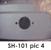 |
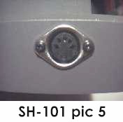
| If done cleanly and correctly, the SH-101 will look like it had MIDI when it came from the factory, as seen in SH-101 pic 5. Trim MIDIJACK wires #9 orange and #10 gray to a suitable length as desired and resolder to the correct pins on the DIN jack. |
 |
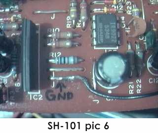 |
11) The black and red wires must be soldered in place to get the ground and power for the MIDIJACK. The standard MIDIJACK installation connects to the regulated power supply inside the synthesizer, usually + 12 or +15 volts, but in this case, we will draw the power for our new MIDI system from the unregulated power coming in the DC IN jack. We will connect to this power source after it has gone through the POWER on/off switch. The #1 black wire should be soldered to a jumper on the top component side of the main SH-101 circuit board. The proper jumper is nearest to the rear of the SH-101, just to the right of IC2 very near the MODULATION GRIP jackboard. This can be seen in SH-101 pic 6. |
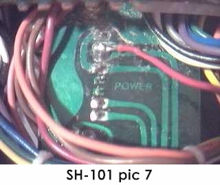 |
See the photo called SH-101 pic 7 which shows the connection point for the #2 red wire at the back of the circuit board holding the POWER on/off switch. This can be done without removing the circuit board from the SH-101. This switch has 8 pins coming through the back of the board. If we refer to the pin nearest the MODULATION GRIP jackboard as pin 1 and the one nearest the BENDER as pin 8, locate the two pins that are already connected to each other by solder, pins 6 and 7, and solder the #2 red wire right between them so it is electrically connected to both of them. Study the photo SH-101pic7 very carefully as you do this, and push some of the SH-101 wires to the side to get a clear view of the pins. |
12) Remove the circuit
board which contains the 9 analog jacks of the SH-101 by sliding it upward
out of the slots that hold it in place. There are no fasteners to
remove, as this board is simply held in place by being trapped between
the top and bottom halves of the synthesizer case. It will still
be connected by numerous wires. This is the PCB that will require
rework and extra connections to make the MIDIJACK work.
| 13) Placing the SH-101 jackboard in a position so you can see the bottom (foil side) of the board in good light, locate the proper cutting and soldering points. Two traces will be cut and four MIDIJACK wires will be soldered to the bottom foil side of this board. The GATE IN and CV IN jacks each have three pins soldered into the board. The center pin is the one that electrically connects to the tip of an inserted 1/8" plug, and also carries the local SH-101 keyboard signal from the switched input to the jack when there is no plug inserted. You will cut the copper circuit board trace coming from the center pin of the CV IN jack. You will also cut the copper circuit board trace coming from the center pin of the GATE IN jack. Carefully cut the traces with an X-Acto knife by digging a nice, even groove to break the signal path. Make sure that there are no foil pieces left hanging around to cause a short circuit later on. SH-101 pic 8 shows the jackboard with these two traces cut by digging a single groove in the lower side of the board. The CV and gate terminals are now isolated and a new wire can be soldered onto each of the terminals that have been isolated, to pass the local keyboard signals through the MIDIJACK board. | 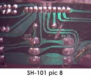 |
14) Solder the MIDIJACK #3 blue wire to the newly isolated CV IN terminal.
15) Solder the MIDIJACK #5 yellow wire to the newly isolated GATE IN terminal.
16) The opposite edge of the jackboard will have the end of 10 pins coming through from the other side, also seen in SH-101 pic 8. Locate the two pins that are connected to the now--cut PCB traces. They were highlighted for visibility in SH-101 pic 8 by scatching the edge of the board just above the pins. If we look at the bottom of the board and number the pins from right to left, they are 1, 2, 3, 4, 5, 6, 7, 8, 9, 10.
17) Solder the MIDIJACK #4 white wire to pin 5.
18) Solder the MIDIJACK
#6 green wire to pin 6.
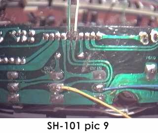 |
19) The finished connections to the analog jackboard can be seen in SH-101 pic 9. A look at this will give some idea of what it will look like when done correctly. Verify that your new connections match the photo. |
20) Carefully examine all cuts and connections made to the analog jackboard for possible short circuits before remounting in the upper SH-101 case.
21) Remount the jackboard in the rear jackpanel by sliding into the original slots, taking care to get the bundles of SH-101 wiring into their original positions so the jacks can be fully seated. The edges of the jacks should be flush with the outside of the case.
22) The MIDIJACK #7 brown wire and #8 violet wire (unless it is used for a special function as described in the Advanced Installation Manual) are not required for for adding MIDI to the Roland SH-101, but it is a good idea not to permanently cut these wires off, as an alternate installation method may become useful later. It is best to wrap the ends of these unused wires with electrical insulating tape and bundle them with the other wires when finishing the installation.
23) The MIDIJACK hardware packet contains nylon cable ties which should be used to tie the MIDIJACK wires into little bundles and to attach them to the factory wires inside the SH-101 now that all connections have been made. This will secure the MIDIJACK wires so they will not rattle and break loose inside the case once the instrument is returned to service.
24) Carefully examine all connections and leads for possible short circuits before reassembling the chassis.
25) Replace the lower case cover and secure it with the 12 small black Phillips screws that hold it in place.
26) Test and calibrate using the procedures described in the MIDIJACK Installation Manual.
27) This installation can be completed in 60-90 minutes. Extra time spent making a perfect installation is time well spent.
With the MIDIJACK, the Roland SH-101 is perfect for computer-controlled
live performances with real-time hands-on sound editing capabilities.
With the MIDIJACK in the MIDI on mode, the envelopes and resonant
filter may be adjusted on the fly while the analog synthesizer voice is
controlled by a MIDI sequencer over an astounding 10-1/2 octave range.
Even when the SH-101 is under MIDI control, the portamento,
bender, and all modulation controls work as always. When the
MIDIJACK is in MIDI off mode, the SH-101 returns to normal use with
the internal sequencer and tiny local keyboard. The user can select
either mode at any time, but may prefer to leave it in MIDI on mode
all the time.
Copyright © 2002 Synhouse Multimedia Corporation