 |
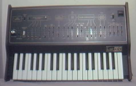
Arp Axxe |
|
Arp Axxe |
|
FREE plans to add MIDI
capability to the
|
 |
The following plans describe a method of adding MIDI capability to the
ARP Axxe analog synthesizer with the Synhouse MIDIJACK. The Axxe
is especially well suited for this modification due to the tiny size of
the MIDIJACK circuit board and the fact that it is the first analog MIDI
retrofit ever made that costs less than the instrument itself! The
ARP Axxe has an extremely stabile oscillator and makes for an excellent
MIDI analog synthesizer with the MIDIJACK. Some drilling is required.
There is plenty of space on the Axxe to mount the MIDIJACK with the provided
hardware. The micro size and black color of the MIDI button are such
a perfect match for the Axxe that it makes it look as if it came from the
factory with the MIDI interface. The installation of the MIDIJACK
in an Axxe is one of the easiest modifications of all. In fact,
with the MIDIJACK, it is possible to convert the Axxe to MIDI without
even removing a single circuit board from the instrument! The correct
analog I/O signals are easy to find and connect to the MIDIJACK.
Like many older American synthesizers, the ARP Axxe has panel-mounted
CV/gate jacks with solder lug terminals and the MIDIJACK wires can simply
be soldered right inside the panel and the whole MIDI conversion job can
be done in 30 minutes. The 1/8" jacks do not even need to be unscrewed
from the back panel. They may be left in place and soldered right
on the spot. This modification reroutes the local keyboard signals
through the computer-controlled analog switching matrix of the MIDIJACK
by extracting the signal and inserting the users' choice of local keyboard
control or MIDI. You can do this yourself if you have a little experience
with electronic repair and the soldering of wires and circuit boards.
If not, these plans may assist a professional repair shop installing
the MIDIJACK for you. The particular installation on which
this document is based was on ARP Axxe serial #2313 0691, the original
version sometimes referred to as the Axxe I. This instrument can
be distinguished from the later model by the fact that it has wood sides
and gold lettering, while the later version has orange lettering.
This installation may be the same for the newer model, but has not
been tested by Synhouse. It is best to download these notes and photos
and print them out on paper to look at while working on the instrument
and make notes and check off the steps as you go. As with any project,
you should completely read and understand each step of the instructions
before starting. All repairs and modifications made to your instruments
will be done at your own risk and Synhouse Multimedia Corporation assumes
no liability for personal injury caused or damage to equipment or loss
of use caused directly or indirectly by the use of these plans. If
in doubt, don't do it!
Instructions:
1) Be sure to have the correct tools and supplies for for the job. If you do not have them, get them. You will need a regular size Phillips screwdriver, a smaller size Phillips screwdriver, needlenose pliers, wire cutters or other flush cut nippers, a hobby knife such as an X-Acto, scissors, a soldering iron, solder, electrical insulating tape, and a black Sharpie permanent ink marking pen. If you intend to mount the DIN jack on the back panel with the rest of the jacks (highly recommended), you will need to use a chassis punch (a small hand tool that safely cuts a clean hole in a metal panel) to make the hole for the DIN jack, and an electric drill with a 1/8" or similar size drill bit to drill holes for the 4-40 hardware used to mount the DIN jack, and also a 1/4" or 5/16" drill bit to make a pilot hole to start the chassis punch. The correct size for mounting a MIDI DIN jack is 14.5 mm metric or 5/8" SAE (.62"/15.9 mm) in American sizes. A chassis punch may be purchased from any good tool or hardware store. If it is more convenient, a punch may be mail ordered via internet or telephone from Mouser Electronics at http://www.mouser.com or (800) 346-6873. The Mouser part number is 586-3803 for the name-brand Greenlee 730-5/8 (about $30). The cheaper house brand part number is 380-0145 (less than $20). The service from Mouser is unpredictable and the house brand ordered by Synhouse for the test installation took three months to be delivered, while the Greenlee part was delivered in one week. Mouser refused to give even a small discount to customers of Synhouse, so no recommendation is deserved or being made here, and any other source you know of to buy this type of tool is highly recommended and certainly a better place to buy from for all of your needs now and in the future. You will also need an 11 mm wrench (for Greenlee) or 1/2" wrench (for the Mouser house brand punch) or adjustable wrench to turn the chassis punch while cutting the hole. An automatic center punch would also be useful. This is an inexpensive spring-loaded pointed punch that can mark your drilling spot without the use of a hammer. Marking the holes with this small indentation will allow you to drill cleanly without slipping and scratching the synthesizer or drilling through your knee.
2) Fully test the ARP Axxe to be converted to MIDI. Be sure that all functions such as the envelope generator work and that the instrument plays in tune while playing along with a known well-tuned instrument such as a newer digital synthesizer or sampler keyboard. If it doesn't work properly without MIDI, it certainly won't work with it.
3) Extreme caution should be taken while working on the ARP Axxe. The unit should be unplugged while open and even then, the power supply may pose some electric shock hazard due to residual voltage in the power supply.
4) Remove the four Phillips screws that hold the chipboard lower case cover in place. They are in the center of the rubber feet. Remove the cover.
5) Turn the synthesizer
upside down and shake out any dust and debris that may have accumulated
inside the instrument over the years.
6) Determine the place
where the MIDIJACK circuit board will be mounted and test fit the board
into its' correct place inside the case. A very inconspicuous place
to mount it is on the left front edge on the synth below the keys so the
MIDI function button can be easily found just below the key for the low
C. This is shown in the photos provided for this installation,
and care must be taken to avoid obstructing the movement of the keys.
It would be quicker and easier to mount it anywhere else, but be
careful to avoid putting the board or wires near the high voltage connections
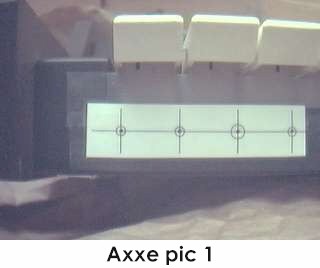
in the right rear of the instrument. Mark the correct mounting holes
on the panel with a pencil, marker, or needle using the paper
drilling template provided with the MIDIJACK Installation Manual.
The photo called Axxe pic 1 shows the paper drilling template in
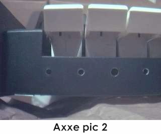
place. The perfect size drill bit for the switch stem and two screw
holes is 9/64", and the perfect size for the scale adjust trimpot
is 3/16". Drill the holes. The photo called Axxe pic 2
shows the location of the newly cut mounting holes.
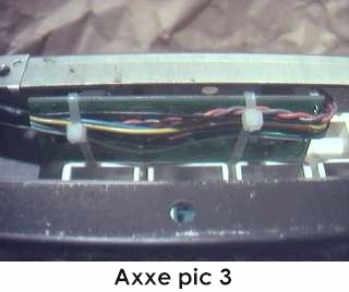
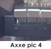
7) Mount the MIDIJACK
board in place. The inconspicuous mounting method can be seen in
Axxe
pic 3 which shows the MIDIJACK board tucked neatly behind the keys.
Nylon cable ties are used to hold the wiring harness close and out of the
way of the key movement. When mounting the MIDIJACK board,
the switch should be fitted so well in the panel that the switch stem will
not wiggle at all once in place. It should not have any free play
but also should not be so tight that it binds. When the switch is
pressed, it should have a definitive "click" and bounce back like
the button on a new VCR. You will never regret spending too much
time on this and good attention to detail will make the perfect MIDIJACK
installation. The hole in the panel that is over the MIDIJACK scale
adjust trimpot should be large enough so a Synhouse Pocket Screwdriver
can fit through the panel for periodic adjustment. The perfect MIDI
control panel installation is shown in Axxe pic 4. Such an
installation will be nearly invisible, yet put the MIDI function
button at the players' fingertips. For the serious Analog User and
synthesizer collector, an ultra-clean installation pays off.
8) Determine the place
that the MIDI input DIN jack will be mounted. A good place to mount
it is on the back panel to the left of the GATE IN jack, as photographed
in this example. There is a lot of room on the rear panel of the
Axxe, so you may mount the DIN jack wherever it suits you best.
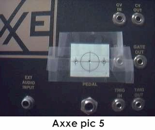
The way to make this look like original ARP factory equipment is to mount
the DIN jack inside the metal panel after marking the bare metal edges
of the hole with a black Sharpie permanent ink marking pen to match the
black finish of the original metal chassis. Use the paper template
to mark the correct spots to drill and cut as shown in Axxe pic 5.
It is advisable to use a chassis punch to make the hole for the DIN jack.
Remember that the DIN jack is to be mounted with the smaller 4-40 hardware
size rather than the larger 6-32 size that secures the main board.
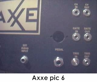
Drill two holes for the screws then drill a slightly larger hole in the
center to act as a pilot hole for the chassis punch. Use the chassis
punch to cut the hole and be sure that the wrench is turning the tool from
inside the Axxe, not outside, so the cutting edge is coming
from the outside. This will ensure that the outer edge is perfectly
smooth. The properly cut mounting holes may be seen in Axxe pic
6. The MIDIJACK hardware packet contains both long and short
4-40 screws for the DIN jack. Use the two long ones for installation
on a thick aluminum panel such as the Axxe. When all three holes
are perfect, put the DIN jack in place inside the chassis and secure
with the two screws from the outside, and the four split washers
and two 4-40 nuts on the inside against the back of the DIN jack and tighten
with a small Phillips screwdriver from the outside and needlenose pliers
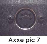
from the inside. These nuts should be very tight as they are going
onto the metal surface of the DIN jack. By using the Synhouse paper
drilling template, a center punch to start the drill, and a
chassis punch, your DIN jack mounting can look perfect like the one
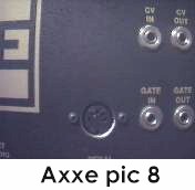
shown in Axxe pic 7. If done cleanly and correctly,
the Axxe will look like it had MIDI when it came from the factory, as in
Axxe
pic 8.
  |
9) The wonderful thing about installing the MIDIJACK in an ARP Axxe is that all six necessary wiring connections can be made to the back of the existing analog interface jacks and a single circuit board in the Axxe (on the top side that is easily accessable) and the entire modification can be performed without removing any boards from the instrument. The Axxe has panel-mounted 1/8" jacks. |
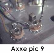
10) The MIDIJACK #1
black and #2 red wires must be soldered in place to get the ground and
power for the MIDIJACK. There is a ground terminal on each of the
1/8'' jacks which connects to the sleeve of the jack, and none of
them have factory wires soldered to them because they are grounded directly
to the chassis. Solder the MIDIJACK #1 black wire to any one of the
ground terminals, such as the one shown in Axxe pic 9,
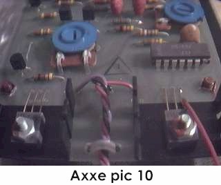
where the MIDIJACK #1 black wire is seen on the right. The correct
regulated +15v power is available on one lead (pin 1) of the +15v power
regulator in the Axxe, which is on the lower edge of the power supply
board in the center of the inside rear panel. The correct connection
can be seen in Axxe pic 10. Solder the MIDIJACK #2 red wire
to this point.
11) Locate the factory
ARP blue wire which is soldered to the back of the CV IN jack. Remove
the wire from the solder terminal by desoldering it. Solder the MIDIJACK
#3 blue wire to the now-empty isolated CV terminal.
12) Solder the MIDIJACK #4 white wire to the now-disconnected factory ARP blue wire. Carefully wrap the solder joint with electrical insulating tape.
13) Locate the factory ARP orange wire which is soldered to the back of the GATE IN jack. Remove the wire from the solder terminal by desoldering it. Solder the MIDIJACK #5 yellow wire to the now-empty isolated gate terminal.
14) Solder the MIDIJACK #6 green wire to the now-disconnected factory ARP orange wire. Carefully wrap the solder joint with electrical insulating tape.
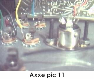
15) Photo Axxe pic
11 shows the inside of the rear of the jackpanel with the DIN jack
mounted and the MIDIJACK wires already connected to the proper points.
A look at this will give some idea of what it will look like when done
correctly.
16) The MIDIJACK #7
brown wire may be cut off at this time because it is not needed for this
installation. Connection of the MIDIJACK #8 violet wire is optional.
It may be used for a special function as described in the Advanced Installation
Manual or cut off at this time. It is not needed for adding MIDI
to the Axxe.
17) The MIDIJACK hardware packet contains nylon cable ties which should be used to tie the MIDIJACK wires into little bundles and to attach them to the factory wires inside the Axxe now that all connections have been made. This will secure the MIDIJACK wires to the inside of the chassis so they will not rattle and break loose inside the case once the instrument is returned to service.
18) Carefully examine all soldered connections for possible short circuits before closing the instrument.
19) Close the instrument and put the chipboard lower case cover in place. Secure it with the four Phillips screws and rubber feet.
20) Test and calibrate using the procedures described in the MIDIJACK Quick Installation Manual.
21) This installation can be completed in 30 minutes.
22) The ARP Axxe has
a trigger circuit separate from the gate circuit to provide multiple note
envelope triggering. This is not required for MIDI operation because
the MIDIJACK has special software to do multiple note triggering like an
ARP or single note triggering like a Moog. The user can select either
mode at any time. For this reason, the local keyboard will
still trigger the envelope generator even with the MIDI activated.
It is impossible to bypass the keyboard triggering completely so it is
probably a good idea not to play the local Axxe keyboard while MIDI is
in use or vice versa.
Copyright © 2000 Synhouse Multimedia Corporation