Applications and Quick Installation Method
All of the
information
required to install the Original MIDIJACK in any compatible synthesizer
is contained in this manual, even if the synthesizer was unknown
to Synhouse at the time of this writing. The complete theory of
application
is described herein. There are no pictures or diagrams in this
manual
because the theory of application is much too broad and conditional to
exist in a single picture. There are eight wires on the Original
MIDIJACK, but some of them will be unnecessary and remain
unconnected. There are no installations which require all eight wires.
In some
cases, as few as four wires will be used and four left
unused. Please read all of this manual before starting work on your
synthesizer.
The Synhouse Original MIDIJACK is a universal MIDI interface that can be added to most any common analog monosynth made by ARP, Moog*, Oberheim, Roland, or Sequential. It also works on many more less common analog synthesizers such as modular systems by Aries, E-mu, Moog, Serge, and rare monosynths such as the Crumar Spirit, Octave Cat and Kitten, and RSF Kobol. The Original MIDIJACK even works where others don't, such as in the EML Electrocomp 101, EMS Synthi and VCS-3 Putney, and in the improperly calibrated Moog Micromoog. The Original MIDIJACK is fully adjustable so that any analog synthesizer with exponential VCOs can be controlled, whether it is 1 volt per octave, .9 volt per octave, .32 volt per octave, or 1.2 volts per octave. The Original MIDIJACK will not work on Yamaha CS-series or most Korg synthesizers. Those Hertz per volt synthesizers are supported by the MIDIJACK II. Although the popular Korg MS10, MS20, and MS50 are generally referred to as being of the Hertz per volt type, they also have a built-in linear-to-exponential converter which puts a volt per octave input on their control panel. This enables compatibility and use with both the Original MIDIJACK MIDI system for volt/octave synthesizers and the MIDIJACK II MIDI system for Hz/volt synthesizers. The Original MIDIJACK can be used by connecting the MIDIJACK wires to the terminals of the FREQ -3V~+3V OCT/VOLT input jack, which is the input to the built-in linear-to-exponential converter. In the alternative, the MIDIJACK II can be used on Korg MS-series synthesizers by making the standard connection to the Hz/volt VCO control voltage input as originally intended, which leaves the FREQ -3V~+3V OCT/VOLT jack and the knob labeled EG/EXT open for other uses. Another advantage of using the MIDIJACK II for the MS-series is that the Hz/volt scaling is inherently more stable over temperature than a typical Moog-type volt/octave VCO design.
*The new Moogiestyle MIDIJACK is designed especially for Moog analog monosynths. This has the same functional description as the Original MIDIJACK, but has built-in automatic software transposition which corrects the inconvenient Moog note reception problem discussed in question 88 on the Analog User FAQs page. The Moogiestyle MIDIJACK is not required for the Moog Source, which works correctly with the Original MIDIJACK.
It helps to
be
familiar with analog synth repair, but the Original MIDIJACK can
be installed by anyone who can solder it to the right points. The
average installation takes about 30 minutes. The board mounts by
drilling only four small holes for the screws, MIDI function
button, and scale adjustment trimmer. A paper drilling template and all
mounting
hardware is included in the Original MIDIJACK hardware packet. The
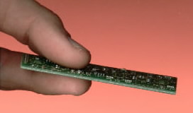
Original MIDIJACK circuit board
itself
is only about the size of a single stick of chewing gum, less
than
3" x 1". Having an extremely low profile, it can be fitted
inside most analog synthesizers between the control panel and the
circuit
board behind it.
These short form instructions will allow anyone to make their own installation in over 90% of all analog synthesizers in existence today, providing that the installer knows enough about the signal flow of the instrument to locate the proper cutting and connection points. More detailed instructions, diagrams, and photographs for many specific popular synthesizer models can be found on the Synhouse website at http://www.synhouse.com under Analog User Modifications. Before starting any work, check the website to see if the installation method for your particular synthesizer model has already been described in detail. If so, it will save time and help prevent mistakes. If not, the following information will help you find the correct connection points for most any Original MIDIJACK-compatible synthesizer. You can do this installation yourself if you have a little experience with electronic repair and the soldering of wires and circuit boards. If not, there are two other installation options: 1) Ship the synthesizer to Synhouse L.A. for Factory Installation or 2) Hire a professional repair shop in your area to install the Original MIDIJACK for you, but be certain that they are experienced in the service of analog synthesizers. Many have tried and failed at first because they were unwilling to read these manuals, causing damage to the synthesizers and resulting in delays and added expense for the customers. If you intend to do your own installation, it is best to download these notes and photos and print them out on paper to look at while working on the instrument and make notes and check off the steps as you go. As with any project, it is best to completely read and understand each step of the instructions before starting work. If you have any questions, please email them to Synhouse before proceeding. All repairs and modifications made to your instruments will be done at your own risk and Synhouse Multimedia Corporation assumes no liability for personal injury caused or damage to equipment or loss of use caused directly or indirectly by the use of these plans. If in doubt, don't do it!
This is how the Original MIDIJACK works:
Standard installations: Most analog monosynths generate a control voltage and gate signal from their own keyboard, route those signals through switches built into the CV/gate jacks on the back of the instrument and then into the synthesizer voice of VCOs and envelope generators. This method will be referred to as plug insertion switching, where the CV and gate input jacks have a normally-closed (connected) single-pole, single-throw switch built into them which is opened (disconnected) when a plug is inserted into the jack. With no plugs inserted, the CV and gate signals generated by the built-in local keyboard goes right through the jacks via the closed switches into the synthesizer voice. With plugs inserted, the built-in local keyboard is disconnected from the synthesizer voice, and the external CV and gate signals go into the synthesizer voice. The Synhouse Original MIDIJACK is a small computer that generates analog control signals and has input wires and output wires that route the local keyboard signals through an internal computer-controlled analog switching matrix. When installed in the correct manner which puts the Original MIDIJACK "downstream" of the existing analog interface jacks, the user may choose between MIDI control or normal use of the keyboard and CV/gate jacks. To install, the user simply disconnects one wire from each of the existing CV and gate input jacks and solders two of the easy color-coded MIDIJACK wires to those jack terminals, and solders the disconnected wires to two more wires on the MIDIJACK wiring harness, then solders two MIDIJACK wires to the synthesizers' own power supply to provide power for the MIDIJACK. When MIDI is activated by pressing the MIDI function button, the analog keyboard is automatically disconnected by the MIDIJACK computer and the analog synthesizer can be controlled from MIDI computer sequencers, keyboards, or any other MIDI controller. When MIDI is turned off, the MIDIJACK automatically removes itself from the signal path and the instrument is returned to normal keyboard and CV/gate operation.
Nonstandard installations: There are two basic types of nonstandard installations. The first type is where the Original MIDIJACK must be installed in a synth that has no CV/gate input jacks to solder onto. With a standard installation type, it's a snap because the signals are right there at the panel and you do not need synthesizer schematics to locate the correct signals. If a synth has no CV/gate input jacks, such as a Roland SH-2000, the MIDIJACK will still work, but the proper signals must be located. This often requires a look at the schematics for the instrument. When the correct points containing the built-in local keyboard CV/gate signals are found, the signals must be tapped into and isolated by disconnecting the wires or cutting the traces on the circuit boards where they are found. Then the MIDIJACK wires are connected to those points. Such an installation is difficult to perform for the first time and should not be attempted by a novice. The second type of nonstandard installation is where the synthesizer does not truly disconnect the keyboard while under external CV/gate control, such as in the Moog Source. In these instruments, the incoming control voltage is summed (or combined) into the local keyboard voltage, and the resulting pitch is a combination of the two, where the local keyboard can be used to transpose the incoming MIDI notes. This type of installation is even easier than the standard type, because there is no local keyboard signal to be bypassed, so there may be two fewer wires to be connected.
For
power, the Original MIDIJACK requires a regulated or unregulated
voltage of at
least 12 volts DC but less than 30 volts DC, and the current
consumption
is very low, approximately 30 mA. The MIDIJACK must have at
least +12 volts DC input to allow it to be stable and put out the top
MIDI note 127 which is +10.58 volts. Nearly any analog
synthesizer
has such a voltage available for use. Special note: Installation
of the Original MIDIJACK in a Roland
SH-101 is slightly more involved than it is with most other
synthesizers
because this battery-powered synth does not provide the correct
voltage. The installer must replace the original Roland AC adapter
power supply
with a different type and use a slightly different internal power
connection
method. Precise details for doing this SH-101 installation can be
found on the Synhouse website at http://www.synhouse.com
under Analog User Modifications.
Please note that the Original MIDIJACK is for MIDI input only. It receives MIDI note messages and generates CV and gate signals to control the synthesizer. It will not allow the built-in local monophonic keyboard to function as a MIDI master controller keyboard and it does not transmit any type of MIDI commands. The CV and gate inputs referred to in the schematic below are only used to allow the MIDIJACK to bypass the built-in local keyboard. When the MIDIJACK is turned off, the computer connects the input wires directly to the output wires as if it were never installed. Where the note says (switched) or (unswitched), switched means that this output signal is internally disconnected by the computer when MIDI is turned off, and unswitched means that it remains connected even when MIDI is off, which may affect some S-Trigger circuits as described later in step 14.
The factory
wiring
harness is color-coded
for easy installation, but the wires may also be located by
counting
from the MIDIJACK #1 black wire (ground) which has the legend H1
silkscreened
on the circuit board next to it, all the way over to the twisted
pair of wires that go to the DIN jack which are #9 orange and #10 gray.
Original
MIDIJACK WIRING
HARNESS CONNECTION SCHEMATIC
H1 (silkscreen marking next to
#1
black wire)
#1 O------------------black
wire/ground-------------------------------------------------------------
#2 O------------------red
wire/+12-+30v regulated or unregulated power input-----
#3 O------------------blue
wire/CV input (for bypass)------------------------------------------
#4 O------------------white
wire/CV output (switched)-----------------------------------------
#5 O------------------yellow
wire/V-Trigger gate input (for bypass)----------------------
#6 O------------------green
wire/V-Trigger gate output (switched)-----------------------
#7 O------------------brown
wire/S-Trigger output (unswitched)--------------------------
#8 O------------------violet
wire/auxiliary MIDI function input------------------------------
#9 O------------------orange
wire/MIDI input--------------------------------DIN jack pin 4
(#9 and #10 wires are a twisted pair)
#10 O------------------gray
wire/MIDI input------------------------------------DIN jack pin
5
Important note: When the MIDI is off, some MIDIJACK wires are internally connected to each other to allow the MIDIJACK to bypass itself. The MIDIJACK #3 blue wire (MIDIJACK CV input) is connected to the MIDIJACK #4 white wire (MIDIJACK CV output) and the MIDIJACK #5 yellow wire (MIDIJACK gate input) is connected to the MIDIJACK #6 green wire (MIDIJACK gate output). When the MIDI is on, MIDIJACK #3 blue wire (MIDIJACK CV input) and the MIDIJACK #5 yellow wire (MIDIJACK gate input) are disconnected internally and the MIDIJACK #4 white wire (MIDIJACK CV output) and MIDIJACK #6 green wire (MIDIJACK gate output) are providing the MIDI-controlled CV/gate signals. What this means is that when the MIDI is off, it is as if the MIDIJACK had never been installed and the synthesizer reverts to the original circuit and signal flow.
The complexity of the Original MIDIJACK installation and the method of operation varies from instrument to instrument, as well as by the level of customization desired by the installer. Some possibilities for custom installations are discussed in the Original MIDIJACK Advanced Installation Manual. Most Moog synthesizers use a slightly different (and easier) method of installation than other brands. Also, some instruments are made of plastic such as the Roland SH-101 and therefore the holes for the DIN jack, switch, trimmer, and mounting screws can be cut easily with the tip of an X-Acto knife, while other synthesizers such as the ARP Odyssey are all metal and will require the use of a power drill and a small hand tool called a chassis punch. Many synthesizers, such as the Sequential Pro-One, have wooden sides, metal rear jackpanel, and plastic surfaces as well. The correct mounting hardware is provided for all applications, whether the synthesizer material is wood, metal, or plastic. There is plenty of space on any analog synthesizer to mount the MIDIJACK with the provided hardware. No matter what the instrument, the installation of the Original MIDIJACK is the easiest analog MIDI modification of all. In some cases, if the synthesizer has CV/gate jacks wired to the rear panel, such as in the Moog MG-1, the MIDIJACK may be installed without even removing a single circuit board from the instrument. The 1/4" jacks do not need to be unscrewed from the back panel. They may be left in place and soldered right on the spot. The correct analog I/O signals are easy to find and connect to the MIDIJACK.
Instructions:
1) Be sure to have the correct tools and supplies for for the job. If you do not have them, get them. A digital multimeter (DMM) is highly recommended for this and any other synthesizer work, although not entirely required for this particular job. If you buy a simple one, you will never regret it, as it will come in handy when testing and fixing audio cables, tuning synthesizers, testing 9v batteries, etc.. One can be purchased from any electronics store, or mail ordered via internet or telephone from a place such as Jameco at http://www.jameco.com or (800) 831-4242. Jameco is a friendly supplier of parts and tools that may be helpful for MIDIJACK installation such as digital multimeters (DMMs, they have part no. 119212 Pocket multimeter for $16.95), wire cutters, solder, and more. You will need a regular size Phillips screwdriver, a smaller size Phillips screwdriver, needlenose pliers, wire cutters or other flush cut nippers, a hobby knife such as an X-Acto, scissors, a soldering iron, solder, electrical insulating tape, and a black Sharpie permanent ink marking pen. If you intend to mount the DIN jack on the back panel with the rest of the interface jacks (highly recommended), you will most likely need to use a chassis punch (a small hand tool that safely cuts a clean hole in a metal panel) to make the hole for the DIN jack, and an electric drill with a 3/32" or similar size drill bit to drill holes for the 4-40 hardware used to mount the DIN jack, and also a 1/4" or 5/16" drill bit to make a pilot hole to start the chassis punch. The correct size for mounting a MIDI DIN jack is 14.5 mm metric or 5/8" SAE (.62"/15.9 mm) in American sizes. A chassis punch may be purchased from any good tool or hardware store. If it is more convenient, a punch may be mail ordered via internet or telephone from Mouser Electronics at http://www.mouser.com or (800) 346-6873. The Mouser part number is 586-3803 for the name-brand Greenlee 730-5/8 (about $30). The cheaper house brand part number is 380-0145 (less than $20). The service from Mouser is unpredictable and the house brand ordered by Synhouse for a test installation took three months to be delivered, while the Greenlee part was delivered in one week. Mouser refused to give even a small discount to customers of Synhouse, so no recommendation is deserved or being made here, and any other source you know of to buy this type of tool is highly recommended and certainly a better place to buy from for all of your needs now and in the future. You will also need an 11 mm wrench (for Greenlee) or 1/2" wrench (for the Mouser house brand punch) or adjustable wrench to turn the chassis punch while cutting the hole. If you choose to mount the DIN jack in the soft plastic portion of a synthesizer chassis, the X-Acto knife will carve out the hole quite easily, and will also make the holes for the screws as well, so no chassis punch, electric drill, or drill bits are needed for this alternate quick mounting method. If you do have a drill available, you may use it carefully at the slowest speed to avoid burning and melting the soft plastic.
2) Fully test the analog synthesizer to be converted to MIDI. Be sure that all functions such as the envelope generator work and that the instrument plays in tune while playing along with a known well-tuned instrument such as a newer digital synthesizer or sampler keyboard. If it doesn't work properly without MIDI, it certainly won't work with it.
3) Extreme caution should be taken while working on a synthesizer which has an AC power cord. Most do, but a few cheapies (then!) such as the Roland SH-101 and MC-202 use an external power supply. If a synthesizer has an AC power cord, it should be unplugged while open and even then, the power supply may pose some electric shock hazard due to residual voltage in the power supply.
4) Remove any screws that hold the upper and lower case halves of the synthesizer together.
5) Open the case and turn the synthesizer upside down and shake out any dust and debris that may have accumulated inside the instrument over the years.
6) Determine the place where the Original MIDIJACK circuit board will be mounted and test fit the board into its correct place inside the case. It is best and safest to mount the MIDIJACK board and route all of its' wires far away from the terminals of the high voltage power transformer, fuse, and power switch. If the MIDIJACK board is to be mounted on a plastic panel, do not use a high-speed power drill or a center punch to mark the holes. Mark the correct mounting holes on the panel with a pencil, marker, or needle using the provided paper drilling template held in place with tape. If the panel of the synthesizer is made of soft plastic, a high-speed power drill will build up friction, generate heat, and burn the plastic permanently. You may use a power drill if you have one that is slow enough, or use an X-Acto knife. Use a standard X-Acto knife blade with the sharp point and twist it in place until it starts to dig a little hole. When it gets close to reaching the other side, you can look inside and see the tip coming through and dig back from the inside as well. A perfectly round hole can be shaped using this technique. If the MIDIJACK board is to be mounted on a metal panel, it is best to use a power drill to make the holes. Mark the correct mounting holes on the panel with a pencil, marker, needle, or center punch using the provided paper drilling template. Carefully drill four holes in the panel.
7) Remove the two black Phillips screws and the six black steel flat washers from the top of the MIDIJACK aluminum mounting brackets. They have temporarily been loosely assembled to the top of the MIDIJACK at the factory to protect the tall plastic switch during shipping and handling. Do not remove the aluminum mounting brackets from the board. They are tightly assembled at the factory. The two Phillips screws are required but the washers are optional parts that may be used to shim the board away from the panel if it is thin metal. If the panel is thick plastic, only one or none may be needed. The switch should protrude through the panel only about 1 or 2 mm. Mount the MIDIJACK in place without fully tightening the screws and try to make sure the holes are the perfect size. The switch should be fitted so well in the panel that the switch stem will not wiggle at all once in place. It should not have any free play but also should not be so tight that it binds. When the switch is pressed, it should have a definitive "click" and bounce back like the button on a new VCR. You will never regret spending too much time on this and good attention to detail will make the perfect MIDIJACK installation. The hole in the panel that is over the MIDIJACK scale adjustment trimmer should be enlarged so the Synhouse Pocket Screwdriver can fit through the panel for periodic adjustment. The screws that secure the MIDIJACK board in place should be tightened very carefully. If the panel is plastic, do not overtighten the screws. If the panel is metal, the shiny edges of the holes can be touched-up with the black Sharpie permanent ink marking pen. Such an installation will be nearly invisible, yet put the MIDI function button right at the players' fingertips. For the serious Analog User and synthesizer collector, an ultra-clean installation pays off.
8) Determine the place that the MIDI input DIN jack will be mounted. The perfect place is on the rear jackpanel along with the existing analog interface jacks. For a metal panel, it is advisable to use a chassis punch to make the hole for the DIN jack. Use the provided paper template held in place with tape to mark the correct spots to drill and cut. Remember that the DIN jack should be mounted with the smaller 4-40 hardware size rather than the larger 6-32 size that secures the main board. Drill two holes for the screws then drill a slightly larger hole in the center to act as a pilot hole for the chassis punch. Use the chassis punch to cut the hole and be sure that the wrench is turning the tool from inside the synthesizer chassis, not outside, so the cutting edge is coming from the outside. This will ensure that the outer edge is perfectly smooth. The MIDIJACK hardware packet contains both long and short 4-40 screws for the DIN jack. Use the two short ones for installation on a thin metal panel. When all three holes are perfect, put the DIN jack in place inside the chassis and secure with the two screws from the outside, and the four split washers and two 4-40 nuts on the inside against the back of the DIN jack and tighten with a small Phillips screwdriver from the outside and the needlenose pliers from the inside. These should be very tight as they are going onto the metal surface of the DIN jack. On a metal panel, the way to make this look like original factory equipment is to mount the DIN jack inside the panel after marking the bare metal edges of the hole with a black Sharpie permanent ink marking pen to match the original black finish of the chassis. If the panel is plastic, the way to make it look like original factory equipment is to mount the DIN jack outside the plastic panel instead of inside the panel as in a normal MIDIJACK installation. This will conceal the somewhat jagged edge of the plastic and prevent the heads of the screws from digging into the panel. To do this, mark one of the two wires (#9 orange or #10 gray) at the terminals of the DIN jack with a marking pen or tape to remember the polarity then desolder both wires. Use the paper template held in place with tape to mark the panel, or turn the DIN jack upside down and use it as its' own template. Do not use a chassis punch (it will crack) or drill (it will melt and burn) to make the hole for the DIN jack. Be absolutely certain that the jack is dead-centered, then proceed with cutting the two holes for the screws with the tip of an X-Acto knife, remembering once again that the DIN jack is to be mounted with the smaller 4-40 hardware size rather than the larger 6-32 size that secures the main board. The MIDIJACK hardware packet contains both long and short 4-40 screws for the DIN jack. The two long ones will probably be best and easiest to use when mounting the DIN jack on a plastic panel. The holes should be barely large enough to fit the screws into and hold the DIN jack (still upside down) completely straight. A hole should then be cut right in the center between the two as a pilot hole for what will be the biggest hole of the three. The center hole should be carefully carved out with an X-Acto knife, preferably from the inside of the case so that if you slip and scratch, no one will see. When all three holes are perfect, put the DIN jack in place with the two screws from the outside, and the two split washers and 4-40 nuts on the inside against the plastic and tighten with a small Phillips screwdriver from the outside and the needlenose pliers from the inside. These should be fairly tight as they are going onto the metal surface of the DIN jack. The wires to the DIN jack may be reconnected by soldering at this time. If the panel is wooden, the way to make it look like original factory equipment is to mount the DIN jack outside the wooden panel instead of inside the panel as in a normal MIDIJACK installation. This will conceal the somewhat jagged edge of the hole in the wood and prevent the heads of the screws from digging into the panel. To do this, mark one of the two wires (#9 orange or #10 gray) at the terminals of the DIN jack with a marking pen or tape to remember the polarity then desolder both wires. Use the paper template held in place with tape to mark the panel, or turn the DIN jack upside down and use it as its' own template. Use a drill bits to make the holes for the DIN jack and the screws. Drill the two holes for the screws, remembering once again that the DIN jack is to be mounted with the smaller 4-40 hardware size rather than the larger 6-32 size that secures the main board. The MIDIJACK hardware packet contains both long and short 4-40 screws for the DIN jack. The two long ones are for installing the DIN jack in a wooden panel up to 5/8" thick such as in a Sequential Pro-One. The holes should be barely large enough to fit the screws into and hold the DIN jack (still upside down) completely straight. A hole should then be drilled right in the center between the two as the large hole for the body of the DIN jack. When all three holes are perfect, put the DIN jack in place with the two screws from the outside, and the two split washers and 4-40 nuts on the inside against the wood and tighten with a small Phillips screwdriver from the outside and the needlenose pliers from the inside. These should be very tight. The wires to the DIN jack may be reconnected by soldering at this time. If done cleanly and correctly, the analog synthesizer will look like it had MIDI when it came from the factory.
9) The MIDIJACK #1 black and #2
red
wires must be soldered in place to get the ground and positive (+)
voltage
to power the MIDIJACK. To do this, you must first find the
correct place to obtain the proper ground and power from the existing
synthesizer
circuitry. There are many places you may connect to get the
ground, but one good one would be at the terminal of one of the CV or
gate
jacks
that carry the ground, the part contacting the sleeve of the
plug. All of the jacks on the synthesizer, including the audio
output, should have a common ground. Any other ground point inside the
instrument, such as on the circuit board, is just as good. Such a point
can
best
be located by using the continuity test function of a digital
multimeter
to ensure that it does conduct to the sleeve of the jacks on the rear
panel. A good place to connect MIDIJACK wires is often the end lead of
a
resistor
or capacitor that is connected to the desired signal, in this
case
ground. The wire from the MIDIJACK harness can simply be wrapped
around the bent end of the lead and soldered in place, making a
strong
solder joint. This will almost always make a solder joint
that
has more mechanical strength than one made by soldering the MIDIJACK
wire
onto a copper circuit trace on the synthesizer circuit board. Another
reliable way to find the correct connection points is by looking at the
schematics in the service manual for your synthesizer if you have
it. Once the ground point is located, solder the MIDIJACK #1 black
wire
in place. Locate the proper positive + power signal in your
synthesizer. It can be any regulated or unregulated DC voltage +12
volts DC or
greater
but below +30 volts, and nearly any analog synthesizer has such a
voltage available. Any ARP, Aries, Oberheim, Roland, or Sequential
synthesizer has a +15 volt regulated power supply. For Moog, the Micromoog
and Multimoog have regulated +15v, and the MG-1, Prodigy, Rogue, and Taurus II
have regulated +12v. It is preferable to use the
regulated
supply when available, and it almost always is. In some
cases, there is no regulated voltage +12 volts or greater and the
unregulated
voltage must be used, such as in the Minimoog which has only
+10v. Extra special techniques for this one can be found in the Advanced
Installation Manual. Once the positive (+) power signal point
is located, solder the MIDIJACK #2 red wire in place. An
ultra-clean
installer may prefer to cut all MIDIJACK wires to the perfect length
for
the application at hand, but other users may prefer to save time
by using the precut, stripped, and tinned wires at their
standard
lengths and there is no electrical reason not to. It is just a
matter
of preference and after the job is done and the synthesizer is put back
into service, who will care?
10) The MIDIJACK CV and gate in
and out wires must be connected next. There are two basic types
of
signal flow in analog synthesizers. Nearly all synthesizers
(except
some Moogs) use plug insertion switching where the keyboard CV is
disconnected
from the synthesizer voice when a plug is inserted into the CV input
jack. To determine if your synth is one of these, play it from the
built-in
local keyboard as usual, then insert a cable (or bare plug) into
the CV input jack and see if the keyboard still plays different notes
for
different keys. If the keyboard does not play and only one pitch
can be heard droning, it has been disconnected because it uses
plug
insertion switching for the CV. A list of some synths of this
type
would be: ARP Axxe
and Odyssey, Moog
MG-1, Prodigy
and Rogue, Roland
SH-101 and other SH-series with CV/gate jacks, and the Sequential
Pro-One. If it does play, it is still connected because
it does not use plug insertion switching for the CV. A list of
some
synths of this type would be: Moog
Micromoog, Minimoog, Multimoog and The
Source. The gate is another matter entirely, where many
synths disconnect the keyboard gate, but Moog synths do
not. Some ARP synthesizers such as the Axxe
or Odyssey are an exception to this test because they still trigger the
envelope generators through a trigger function even though they use
plug
insertion switching for both the CV and the gate. For more
details, read the ARP articles on the Synhouse website at http://www.synhouse.com under
Analog User Modifications.
Physically, there are two basic types of analog interface jacks. Your synthesizer has one of them, unless it has no jacks at all, as discussed under nonstandard installations. The first type are panel-mount jacks. These are the older type of jacks which look like the ones used on an electric guitar. They are held in place on the jackpanel by a large nut outside and have solder lug terminals on the inside where wires are soldered to them. The second type are PC-mount jacks. These are the newer type that are inserted into the PC board (printed circuit board) and soldered directly to the printed copper circuit traces on the lower side of the circuit board. Look at the soldered connections which are at the back of the CV/gate input jacks and you will be able to determine which type you have to work with. A MIDIJACK installation will be very easy if the synthesizer has panel-mount jacks as most older American synthesizers do. If the synthesizer has PC-mount jacks, it will take a little more thought and analysis beforehand and a little cutting of traces on the circuit board to isolate the signals, but very neat work can be done that will not sacrifice the electronic integrity or mechanical strength of the synthesizer.
These instructions will first
describe
installation in the type of analog synthesizer which has panel-mounted
jacks with solder lug terminals. At the end of this
section, before step 14, there will be a general description of how the
same
work would be performed on a synthesizer which has PC-mount jacks.
11) The CV in and out wires
must
be connected. Look at the soldered connections which are at the
back
of the CV input jack. On nearly any analog synthesizer with
CV/gate
jacks, the sleeve is grounded and the keyboard control voltage
coming
from the synthesizer's own keyboard is sent in a wire (the IN wire) to
a terminal on the CV input jack and routed through a normally closed
switch
inside the jack that normally connects the signal to another terminal
on
the jack that sends it (the OUT wire) to the analog synthesizer voice
(VCO
and VCF) when nothing is plugged into the jack. When a plug is
inserted
into the jack, the connection is broken (from the IN wire) and
the
local keyboard control voltage is now disconnected. The tip of
the
inserted plug is now sent out the terminal to the analog synthesizer
voice
(through the OUT wire) instead of the local control voltage. You
must locate the wire which is the OUT wire at the back of the CV input
jack. The best way to do this is to insert a cord or bare plug
into
the CV input jack and use the continuity test function of a multimeter
to probe all of the solder terminals to find the one that is the OUT
wire
going to the synth voice. This will be the one that
conducts
directly to the tip of the inserted plug. You should now be able
to determine that this OUT wire is no longer conducting to the IN wire
with a plug inserted. When you find the OUT wire, remove it
from the solder terminal by desoldering it. Solder the MIDIJACK
#3
blue wire (MIDIJACK CV input) to the now-empty isolated CV terminal.
12) Solder the MIDIJACK #4 white wire (MIDIJACK CV output) to the OUT wire that you have just disconnected from the terminal. Carefully wrap the solder joint with electrical insulating tape. This will put the MIDIJACK "downstream" from the CV input jack, allowing the synthesizer to be MIDI-controlled by the MIDIJACK, while still allowing the keyboard and analog interface jacks to work as they always have.
Important note: If this concept
of
switching and bypassing the CV signals to put the the MIDIJACK
"downstream"
from the CV input jack is not immediately and completely clear to
you, you should refer the installation to Synhouse for Factory
Installation, or to another qualified professional
synthesizer
repair shop who can easily install the MIDIJACK in 30 minutes without
problems
or damage to your instrument.
13) The gate wires must be
connected
now. The MIDIJACK is a universal MIDI interface that supports
many
synthesizers. Although there are hundreds of different
synthesizers, there are only two types of gates used to trigger the
envelope
generators. The MIDIJACK supports both, but the installation method
differs
for
each of these two types. Both types of installations are
described
here. Read this section carefully. Moog synthesizers
generally
use an S-Trigger (shorting trigger) which is nearly the opposite of all
other analog synthesizers which use a V-Trigger (+ positive
voltage). For this reason, the MIDIJACK creates a +11v trigger which
works
perfectly for all synthesizers except Moog and outputs it via the
MIDIJACK
#6 green wire, and also creates an inverted version of this
signal
and puts it at the MIDIJACK #7 brown wire (S-Trigger output,
unswitched). When a MIDI note is active, the MIDIJACK #6 green wire is
+11v
while
the MIDIJACK #7 brown wire is 0v. When there is no MIDI note
active, the MIDIJACK #6 green wire is 0v while the MIDIJACK #7 brown
wire is
+11v. They are exactly opposite, and it is easy to remember by color
which
wire is the Moog wire because the most famous Moog synthesizer made was
the Minimoog, made of wood and it was brown. The Moog wire
is brown just the same. The MIDIJACK installation methods differ
for these two types and both are described here.
To install in a V-Trigger synthesizer
(nearly
any synthesizer except some Moogs): The gate in and out wires
must
be connected. Look at the wires which are at the back of the gate
input jack. On nearly any analog synthesizer with CV/gate
jacks, the sleeve of the jack is grounded and the keyboard gate voltage
coming
from the synthesizer's own keyboard is sent in a wire (the IN wire) to
a terminal on the gate input jack and routed through a normally closed
switch inside the jack that normally connects the signal to another
terminal
on the jack that sends it (the OUT wire) to the analog synthesizer
voice
(ADSR or other envelope generator) when nothing is plugged into the
jack. When a plug is inserted into the jack, the connection is broken
(from
the IN wire) and the local keyboard gate voltage is now
disconnected. The tip of the inserted plug is now sent out the terminal
to the analog
synthesizer voice (through the OUT wire) instead of the local gate
voltage. You must locate the wire which is the OUT wire at the back of
the gate
input jack. The best way to do this is to insert a cord or bare
plug
into the gate input jack and use the continuity test function of a
multimeter
to probe all of the solder terminals to find the one that is the OUT
wire
going to the synth voice. This will be the one that
conducts
directly to the tip of the inserted plug. You should now be able
to determine that this OUT wire is no longer conducting to the IN wire
with a plug inserted. When you find the OUT wire, remove it
from the solder terminal by desoldering it. Solder the MIDIJACK
#5
yellow wire (MIDIJACK gate input) to the now-empty isolated gate
terminal. Solder the MIDIJACK #6 green wire (MIDIJACK gate output) to
the OUT
wire
that you have just disconnected from the terminal. Carefully wrap
the solder joint with electrical insulating tape. This will put
the
MIDIJACK "downstream" from the gate input jack, allowing the
synthesizer
to be MIDI-controlled by the MIDIJACK, while still allowing the
keyboard
and analog interface jacks to work as they always have.
Special note: If your synthesizer
is of the type which has both V-Trigger and S-Trigger inputs (such as
a Moog Rogue),
always
use the V-Trigger input and install as described in the previous
paragraph. The V-Trigger method is always a better method, with or
without
MIDI. If your synth is S-Trigger only, follow the directions in the
next
paragraph.
To install in an S-Trigger
synthesizer
such as a Moog: Most Moog synthesizers never completely
disconnect
the keyboard from the trigger circuit with a switched jack as they
should. For the S-Trigger, they often use a Cinch-Jones two-blade
connector
that looks similar to a male 115 VAC power plug, and this
primitive
type of connector cannot incorporate a switch. In some
cases, such as on a later model Moog Prodigy, they use a 1/4" jack for
the
S-Trigger input, but still do not disconnect the keyboard. For this
reason, the local keyboard will still trigger the
envelope
generator even with the MIDI activated, or while external CV/gate
control is being used. The MIDIJACK #7 brown wire (S-trigger
output, unswitched) must then be connected in parallel with the
existing
trigger
wire, using a small signal diode to isolate the signal so the
local
keyboard will still work when the MIDI is turned off. The correct
type of diode is included with the MIDIJACK in the accessory
packet, but may also be purchased locally at any electronics store such
as
Radio
Shack as a 1N914 or 1N4148 or equivalent type of switching diode. You
must now find the S-Trigger signal. For the Cinch-Jones type
of connector, one blade is wider than the other. The
S-Trigger
input is a female jack with two slots. The wide blade slot is pin
1 and is usually connected to ground on the instrument. The
narrower
blade slot is pin 2 and that is the OUT wire for this purpose. For
the 1/4" jack type, the tip will sometimes be the OUT wire, but
sometimes it will be a stereo jack as in The
Source, which uses a different method entirely. Precise
details for doing this installation on The
Source can be found on the Synhouse website at http://www.synhouse.com under
Analog User Modifications. Whichever type of connector your
synth has, locate the wire which is the OUT wire at the back of
the
S-trigger connector solder terminals. Just to be sure, if
there
are two terminals and you are not sure which one, you can use the
continuity test function of a multimeter to probe the solder
terminals. The one that is connected to ground when the synth is
unplugged is not
the one. When you find the correct wire soldered to the
terminal, leave it connected as it is and solder the anode end of the
diode (the
end AWAY from the little black band) to this point and solder the
MIDIJACK
#7 brown wire to the cathode end of the diode (the end with the little
black band). In summary, the MIDIJACK #7 brown wire goes to
the band end of the diode, the other end of the diode goes to the
same terminal on the trigger jack that still has the S-Trigger OUT wire
soldered to it. There will now be a factory wire AND a diode
connected
to this terminal of the jack. The MIDIJACK #5 yellow wire and #6
green wire are not required for for adding MIDI to an S-Trigger
Moog, but it is a good idea not to permanently cut these wires off, as
an alternate installation method may become useful later. It is
best
to wrap the ends of these unused wires with electrical insulating tape
and bundle them with the other wires when finishing the installation.
A general description of how the same MIDIJACK CV/gate connections would be performed on a synthesizer which has PC-mount jacks: PC-mount jacks generally have the contacts and switching mechanism inside a sealed case and therefore a continuity tester (DMM or other) may be necessary to find the correct IN and OUT connection points. It will be very difficult to trace this type of circuit with your eyes. It is definitely best to leave the PC-mounted jack securely solder-mounted right where it is, and make your connections elsewhere in the circuit. For instance, if you locate the OUT terminal on the CV input jack by inserting a plug and finding that the tip of the plug conducts to the OUT terminal (using a continuity tester), you would trace the copper circuit trace from the OUT terminal to whatever it goes to on the other end, something else on the same PC board such as a resistor lead. When that is found, it would be best to solder the MIDIJACK #3 blue wire (MIDIJACK CV input) directly to the OUT terminal on the lower side of the PC board, and solder the MIDIJACK #4 white wire (MIDIJACK CV output) directly to that resistor lead on the other end (which might be easiest to do on the top side of the PC board). After that, break the original factory connection to the OUT terminal by cutting the copper circuit trace with an X-Acto knife somewhere between the two solder points. This allows the connections to be made without weakening the mounting strength of the PC-mount jack. An excellent example of this type of work is shown in photos that can be found on the Synhouse website at http://www.synhouse.com under Analog User Modifications in the section describing the MIDIJACK installation in a Roland SH-1 and the SH-101. An experienced synthesizer technician will actually prefer to do this type of installation with PC-mount jacks because the concepts are both familiar and simple and the end result will be a very neat installation, while a novice installer will prefer the simplicity of connecting to the solder lugs on panel-mount jacks.
Important note: As previously
mentioned
at the beginning of this manual, your synthesizer may require a
nonstandard
MIDIJACK installation because it has no CV/gate input jacks to solder
onto, such as a Moog
Prodigy
without jacks. If your synth has no CV/gate input jacks, the
MIDIJACK will still work, but the proper signals must be located
within the circuitry of the synth voice. You will need to find
the
point which has the local keyboard CV and cut it off to break the
circuit. One half of this broken connection will be the signal coming
from the
keyboard
circuit, and the other half will be going into the synth
voice. Please note that the term "synth voice" does not mean "VCO
only". This needs to be the point in the circuit that feeds the
keyboard
voltage
into the VCO and the VCF keyboard tracking amount pot or switch,
otherwise you might end up with no keyboard tracking while receiving
MIDI
notes. Keyboard tracking becomes more useful than ever when the
MIDIJACK
has expanded your synthesizer to a full 128 MIDI notes, a range
greater
than ten octaves. The gate signal must also be located, tapped, and
isolated. Finding these points in the circuit often requires
a look at the schematics for the instrument. When the correct
points
containing the built-in local keyboard CV/gate signals are found, the
signals must be tapped into and isolated by disconnecting the wires
or cutting the traces on the circuit boards where they are found. Then
the MIDIJACK wires are connected to those points. Such an
installation
is difficult to perform for the first time and should not be attempted
by a novice. If any part of this concept of tapping and isolating
the CV/gate signals to put the the MIDIJACK "downstream" from the
built-in
local keyboard is not immediately and completely clear to you, you
should refer the installation to Synhouse for Factory
Installation, or to another qualified professional
synthesizer
repair shop who do the work without risk of damage to your instrument.
Warranty notice: The MIDIJACK is intended for a standard installation which creates an electrical connection identical to external CV/gate control. When correctly done, the synthesizer will draw almost no current whatsoever through the MIDIJACK #4 white wire (MIDIJACK CV output). When measured with an Ammeter, the current drawn should be less than 1 mA. If it is more than 5 mA, something is seriously wrong and poor performance or damage may be the result of this improper connection. The provided warranty and technical support do not cover improper installations. A handy way to test this application before making all the cuts and connections is to temporarily solder the MIDIJACK output wires to the appropriate plugs and the power inputs to the synth power supply and plug into the CV/gate jacks externally. This is electrically identical to what the connections will be behind the jacks (except for the keyboard bypassing by the MIDI on/off as described in "This is how the Original MIDIJACK works" at the beginning of this manual).
14) Now that all connections have been made, it is a good idea to secure the MIDIJACK wires inside the synthesizer so they will not rattle and break loose inside the case once the instrument is returned to service. The MIDIJACK hardware packet contains nylon cable ties which can be used to tie the MIDIJACK wires to the original wire bundles inside the synthesizer (NOT THE AC POWER WIRES!!!). Additionally, you may cut short pieces of electrical insulating tape and use them to secure the MIDIJACK wires to the inside of the synthesizer chassis if there are not enough places to wrap cable ties. You may wish to read the Original MIDIJACK Advanced Installation Manual before deciding what to do with any unused wires. With any installation, some wires will remain unused. It is a good idea not to permanently cut these wires off, as an alternate installation method may become useful later. It is best to wrap the ends of these unused wires with electrical insulating tape to prevent electrical shorts and bundle them with the other wires.
15) Carefully examine all soldered connections for possible short circuits before powering or closing the instrument.
16) Close synthesizer case halves and secure with original screws.
17) Test the synthesizer under MIDI control with some type of MIDI controller as described in the Original MIDIJACK Analog User Manual.
18) Analog Calibration Mode: When the MIDIJACK-equipped synthesizer is powered-up with MIDI On Mode previously selected before last power-down, the on-board computer causes it to automatically and silently go into the Analog Calibration Mode where the MIDIJACK #4 white wire (MIDIJACK CV output) puts out the voltage of the highest MIDI note, MIDI note 127, which is +10.58 volts. This can be adjusted with the scale adjustment trimmer. This note will not be heard at the audio output of the synthesizer because the gate is not active during Analog Calibration Mode. The scale adjustment trimmer affects the musical intonation of the analog synthesizer while it is under MIDI control and the easiest and most precise way to adjust the setting is by putting the instrument into the Analog Calibration Mode and checking the voltage on the MIDIJACK #4 white wire (MIDIJACK CV output) with a digital multimeter (DMM). Intonation is not overall tuning, but rather the pitch interval between keys of the synthesizer. The scale adjustment trimmer is less than one inch away from the MIDI function button and may be adjusted by inserting a small flatblade screwdriver into the control panel opening. A Synhouse Pocket Screwdriver fits perfectly. The scale adjustment trimmer is factory set to be +10.58 volts during Analog Calibration Mode, and may need to be readjusted slightly to compensate for a synthesizer that is improperly calibrated or if the trimmer has accidentally been turned away from the factory setting during transport or installation. If the pitch of the synthesizer notes are too close together at the +10.58v setting, the trimmer should be turned up (slightly clockwise), and if the notes are too far apart and get more and more sharp as you go up the keyboard, the trimmer should be turned down (slightly counterclockwise). When MIDI notes of C are sent, such as MIDI notes 36, 48, 60, 72, 84, and 96, the voltage will be one volt per octave putting out the respective voltages of 3.00v, 4.00v, 5.00v, 6.00v, 7.00v, and 8.00v, depending upon the current MIDI Transpose Select Mode setting. If set to a transpose interval of -36 half steps (3 octaves down), those voltages should be, respectively, 0.00v, 1.00v, 2.00v, 3.00v, 4.00v, and 5.00v. This test will show the precision of the MIDIJACK output and determine if your synthesizer is really calibrated to 1v/octave. If these voltages are seen to be perfect, but the synthesizer does not play in tune while under MIDI control, then the synthesizer is out of calibration. The truth: Many synthesizers were factory made and adjusted to play in tune with their own keyboard, but the external CV/gate inputs were not actually calibrated at all. In many cases, the claimed 1v/octave sensitivity is way off. If no digital multimeter is available when calibration is needed, the scale adjustment trimmer may be set by ear if you have a good sense of pitch. A MIDI controller keyboard should be connected with a MIDI cable to the MIDIJACK and the audio output of the analog synthesizer to a sound system for monitoring. The MIDIJACK should be in MIDI On Mode and set to the same MIDI channel as the MIDI controller keyboard. While playing alternating notes on the MIDI controller keyboard that are an octave apart, the user can turn the scale adjustment trimmer very slowly until the proper one-octave interval is heard and the entire keyboard plays in tune. It may be easiest to hear the tones clearly by adjusting the analog synthesizer so that the filter is open with the frequency set to maximum, the resonance (also known as "Q", or emphasis) set to minimum, and the envelope generators set to sustain, without any vibrato on the oscillators. An extra help would be to use a MIDI synthesizer or sample playback keyboard as the MIDI controller and listen to its sound output as a reference tone to match the analog synthesizers intonation while adjustments are being made. A low note may be played on the MIDI keyboard while the analog synthesizer's master tuning knob is adjusted to bring the two sound sources into tune. Next, play higher octave intervals of that note, and slowly turn the MIDIJACK scale adjustment trimmer until the entire keyboard plays in tune. Analog calibration should only be performed occasionally, as overuse of the scale adjustment trimmer may cause excessive wear and premature failure of the part.
20) This Original MIDIJACK installation can be completed in 20-30 minutes for many analog synthesizers. Some synthesizers that require removal of PC boards for the purpose of cutting traces may take from 60 minutes or more. Extra time spent making a perfect installation or other improvements to the machine is time well spent.
Analog User Support
Need
help? Technical support for Synhouse products is available online for
Analog
Users. Send help requests to Synhouse via e-mail.
Application problems will be researched
and answered via email. Some
answers
to common problems can be found on the Synhouse website at http://www.synhouse.com under
Analog User FAQs.
Warranty
The Original
MIDIJACK
Quick Installation Manual must be read fully and understood completely
to qualify for warranty coverage and technical support. The
MIDIJACK
is warranted against defects in parts and manufacture for a period of
90
days from the date of purchase. Warranty becomes void if in the
opinion
of Synhouse Multimedia Corporation the MIDIJACK has been subjected to
unauthorized
service, modification, or unintended installation or
usage. No liability is assumed by Synhouse Multimedia Corporation for
any loss
or damage, direct or indirect, resulting from the use of or
inability to use the MIDIJACK.
Copyright © 3/5/2009 Synhouse Multimedia Corporation