 |
Moog Micromoog Module |
|
Moog Micromoog Module |
|
FREE plans to convert the Moog Micromoog to a tabletop analog MIDI module and audio processor with the Synhouse MIDIJACK! |
 |
The following plans describe a method of removing the keyboard and adding
MIDI capability to the popular Moog Micromoog analog synthesizer with the
Synhouse MIDIJACK. This allows the instrument to be converted to
a more convenient tabletop MIDI sound module that is only one-third the
original size, or upright module that can be set upright on top of
another instrument, put into a rack-mount configuration, or
mounted on a studio wall to save space. This is especially useful
if the Micromoog is in bad condition with broken keys, worn-out ribbon
controller, and damage to the end panels. The original factory
keyboard glide on the Micromoog never worked when the instrument was externally
controlled by CV input. With the following rework modifications,
the glide will work while the instrument is under MIDI control. Some
drilling is required to do the cleanest possible installation, unless
the user prefers to mount the DIN jack to the plastic front panel of the
instrument. There is plenty of space on the Micromoog to mount the
MIDIJACK with the provided hardware. The micro size and black color
of the MIDI button are such a perfect match for the Micromoog that it makes
it look as if it came from the factory with the MIDI interface. Beginners
beware, the conversion of a Micromoog to a MIDI sound module is one
of the most difficult MIDIJACK installations of all. This modification
reroutes the CV input signal through the computer-controlled analog switching
matrix of the MIDIJACK by extracting the signal and inserting the users'
choice of external CV jack control or MIDI. The particular installation
on which this document is based was on Moog Micromoog serial #3379,
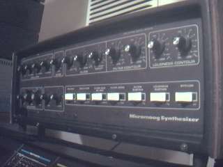
other revisions may be different. The photo found at the top of this
page shows an overall view of such an instrument. It is best to download
these notes and photos and print them out on paper to look at while working
on the instrument and make notes and check off the steps as you go.
As with any project, it is best to completely read and understand
each step of the instructions before starting. All repairs and modifications
made to your instruments will be done at your own risk and Synhouse Multimedia
Corporation assumes no liability for personal injury caused or damage to
equipment or loss of use caused directly or indirectly by the use of these
plans. If in doubt, don't do it!
Instructions:
1) Be sure to have the correct tools and supplies for for the job. If you do not have them, get them. You will need a regular size Phillips screwdriver, a smaller size Phillips screwdriver, needlenose pliers, wire cutters or other flush cut nippers, a hobby knife such as an X-Acto, scissors, a soldering iron, solder, electrical insulating tape, and a black Sharpie permanent ink marking pen. If you intend to mount the DIN jack on the back panel with the rest of the inputs (highly recommended), you will need to use a chassis punch (a small hand tool that safely cuts a clean hole in a metal panel) to make the hole for the DIN jack, and an electric drill with a 3/32" or similar size drill bit to drill holes for the 4-40 hardware used to mount the DIN jack, and also a 1/4" or 5/16" drill bit to make a pilot hole to start the chassis punch. The correct size for mounting a MIDI DIN jack is 14.5 mm metric or 5/8" SAE (.62"/15.9 mm) in American sizes. A chassis punch may be purchased from any good tool or hardware store. If it is more convenient, a punch may be mail ordered via internet or telephone from Mouser Electronics at http://www.mouser.com or (800) 346-6873. The Mouser part number is 586-3803 for the name-brand Greenlee 730-5/8 (about $30). The cheaper house brand part number is 380-0145 (less than $20). The service from Mouser is unpredictable and the house brand ordered by Synhouse for the test installation took three months to be delivered, while the Greenlee part was delivered in one week. Mouser refused to give even a small discount to customers of Synhouse, so no recommendation is deserved or being made here, and any other source you know of to buy this type of tool is highly recommended and certainly a better place to buy from for all of your needs now and in the future. You will also need an 11 mm wrench (for Greenlee) or 1/2" wrench (for the Mouser house brand punch) or adjustable wrench to turn the chassis punch while cutting the hole. If you choose to mount the DIN jack in the soft plastic portion of the Micromoog chassis, the X-Acto knife will carve out the hole quite easily, and will also make the holes for the screws as well, so no chassis punch, electric drill, or drill bits are needed for this alternate quick mounting method.
2) Fully test the Moog Micromoog to be converted to MIDI. Be sure that all functions such as the envelope generator work and that the instrument plays in tune while playing along with a known well-tuned instrument such as a newer digital synthesizer or sampler keyboard. If it doesn't work properly without MIDI, it certainly won't work with it.
3) Extreme caution should be taken while working on the Moog Micromoog. The unit should be unplugged while open and even then, the power supply may pose some electric shock hazard due to residual voltage in the power supply.
4) Understand the different main operations that are involved: A) The physical cutting of the instrument into a new configuration, removing the keyboard, ribbon controller, and modulation wheel. B) Electronically removing the keyboard, ribbon controller, and modulation wheel from the original circuit so the Micromoog will work without them. C) Defeating the original glide circuit and isolating the glide pot for use in a new active glide circuit. D) Making a new active glide circuit and installing it. E) Installing the Synhouse MIDIJACK.
5) Open the case and turn the synthesizer upside down and shake out any dust and debris that may have accumulated inside the instrument over the years.
6) Perform the physical modification which cuts off the keyboard, modulation wheel, and ribbon controller and put the instrument into the desired configuration. Remove the main PC board from the instrument by removing the knobs and switch caps and unscrewing it from the top panel by removing the nuts holding it in place.
7) There are a number of Molex-style connectors along the front edge of the PC board, numbered from the left. The 5-pin female keyboard connector should have been removed from P2, the second male connnector from the left. P2 actually has two female connectors plugged in, a four-circuit and a five-circuit. Leave the four-circuit connector in place.
8) The keyboard must
be electronically substituted in the circuit by adding a new resistor.
On P2, the pins are numbered from the left. Add a 3.1K-1% resistor
to P2-pin 9 and connect the other end of the resistor to P2-pin 7.
Connect P2-pin 5 directly to P2-pin 7. Resistor R240 is a 1K resistor
and is no longer needed. Cut it out of the circuit. Although
the PC board is of fairly good quality, the silkscreen is terrible,
making it difficult to read the component designations, so use extra
care to be sure you have located the correct parts. It would probably
be best to use a continuity tester to buzz out alternate locations on the
board to make these conections rather than trying to solder onto the Molex
pins. The keyboard has now been bypassed.
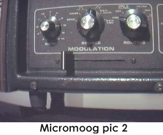
9) The modulation
wheel must be bypassed. Cut the wires that had once been attached
to it. You will need a 10K potentiometer which will be used to make
a modulation depth control. It is preferable to use an audio taper
pot for the finest control in the useful range. On the Micromoog
modified for this article, a 70 mm long-throw slider (fader) was
used and mounted below the three knobs in the modulation section sliding
from left to right, providing very smooth control previously unattainable
with the Micromoog. This new slider is shown in Micromoog pic
2. Connect the cut brown wire coming from P2-pin 1 to the high
leg terminal of the new pot. Connect the cut black wire coming from
the modulation jack at the back of the instrument to the wiper terminal
of the new pot. Connect the low leg terminal of the new pot to ground,
which appears at the P1-pin 3 green wire, among other places.
This is your new modulation depth control and should be mounted on the
panel after all other work is finished. Tape up all other loose wires
to prevent short-circuits.
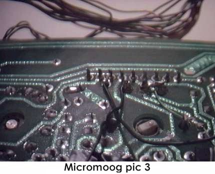
10) The original glide
circuit was integrated into the local analog keyboard sample and hold circuit
and must be defeated by isolating the glide pot for use in a new active
glide circuit. The glide pot is R251, a 5 meg audio taper pot.
One terminal of the pot is not connected to the circuit. Locate the
two terminals that are connected via PC board traces and cut the two copper
PC board traces so they no longer connect to the circuit. This isolates
the pot, but you must close the circuit by wiring the two traces
that were going to the pot to each other. The synthesizer glide has
now been bypassed. Wire the two terminals on the left side of the
pot together. This pot is now configured as a variable resistor (so
the resistance goes up when turned clockwise) isolated from the rest of
the circuitry. This work can be seen in the photo called Micromoog
pic 3.
11) A new active exponential
glide circuit must be made from new components. You will need an
op amp, a .1 uF ceramic bypass capacitor and another timing capacitor (electrolytic
or other) of approximately .47 uF an at least a 15 volt rating. The
junction of the timing capacitor and the newly-isolated pot should
be connected to the op amp configured as a buffer-follower. This
buffered output will go to the VCO. This will put a lag generator
between the MIDIJACK and the VCO. If the op amp used is of the standard
older variety such as an LM358, the negative power pin should be
connected to the -15V negative supply in the synthesizer (such as at the
frontmost lead of R360, an unusual-looking resistor between the filter
cutoff and emphasis pots) and not the ground. If this is not done,
the op amp will be unable to reach ground, causing a tuning problem
that will be accentuated when the MIDIJACK is MIDI transposing -36 for
super deep bass, but the synthesizer octave select is set to 32'.
Build the tiny new circuit on a little piece of perfboard and wire the
power connections to the Micromoog board. There should be an input
and output to this circuit that will be left disconnected for now.
Mount the little circuit somewhere, such as in the screw holes that
were never used on the release slide switch. If any of this terminology
is not immediately clear to you, you should not even try this modification!
12) It is now time to install the Synhouse MIDIJACK. Determine the place where the MIDIJACK circuit board will be mounted and test fit the board into its correct place inside the case. The best place to mount the MIDIJACK board on the Micromoog is front and center on the plastic panel below the release switch, with the MIDI button on the right and the scale adjust trimmer on the left. Mark the correct mounting holes on the panel with a pencil, marker, or needle using the paper drilling template provided with the MIDIJACK Installation Manual. Do not use a drill. This portion of the panel of the Micromoog is made of soft plastic and a drill, even on its' slowest speed, will build up friction, generate heat, and burn the plastic permanently. Use a standard X-Acto knife blade with the sharp point and twist it in place until it starts to dig a little hole. When it gets close to reaching the other side, you can look inside and see the tip coming through and dig back from the inside as well. A perfectly round hole can be shaped using this technique. The threaded stud that holds the front edge of the PC board may interfere with the mounting of the MIDIJACK board, but may be bent to the side easily without affecting the instrument.
13) Mount the MIDIJACK
in place without fully tightening the screws and try to get the perfect
size holes by twisting the X-Acto knife but do not make them too big.
The switch should be fitted so well in the panel that the switch stem will
not wiggle at all once in place. It should not have any free play
but also should not be so tight that it binds. When the switch is
pressed, it should have a definitive "click" and bounce back like
the button on a new VCR. You will never regret spending too much
time on this and good attention to detail will make the perfect MIDIJACK
installation. The hole in the panel that is over the MIDIJACK scale
adjust trimpot should be enlarged so a Synhouse Pocket Screwdriver can
fit through the panel for periodic adjustment. The screws that secure
the MIDIJACK board in place should be tightened very carefully. The
panel is plastic so do not overtighten the screws. Such an installation
will be nearly invisible, yet put the MIDI function button at the
players' fingertips. For the serious Analog User and synthesizer
collector, an ultra-clean installation pays off. It may be
easiest to remove the screws and let the MIDIJACK board hang loose until
the wiring is done.
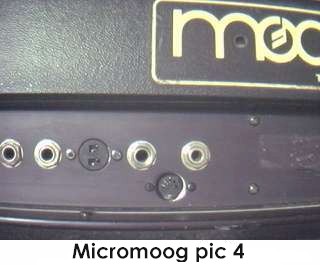
14) Determine the
place that the MIDI input DIN jack will be mounted. The perfect place
is on the rear jackpanel 3/4" below the audio and modulation input jacks.
See photo called Micromoog pic 4. The way to make this look
like original Moog factory equipment is to mount the DIN jack inside the
metal panel after marking the bare metal edges of the hole with a black
Sharpie permanent ink marking pen to match the black finish of the original
metal chassis. Use the paper template to mark the correct spots to
drill and cut. It is advisable to use a chassis punch to make the
hole for the DIN jack. Remember that the DIN jack is to be mounted
with the smaller 4-40 hardware size rather than the larger 6-32 size that
secures the main board. Drill two holes for the screws then drill
a slightly larger hole in the center to act as a pilot hole for the chassis
punch. Use the chassis punch to cut the hole and be sure that the
wrench is turning the tool from inside the Micromoog, not outside,
so the cutting edge is coming from the outside. This will ensure
that the outer edge is perfectly smooth. The MIDIJACK hardware packet
contains both long and short 4-40 screws for the DIN jack. Use the
two long ones for installation on a thick aluminum panel such as the Micromoog.
When all three holes are perfect, put the DIN jack in place inside
the chassis and secure with the two screws from the outside, and
the four split washers and two 4-40 nuts on the inside against the back
of the DIN jack and tighten with a small Phillips screwdriver from the
outside and the needlenose pliers from the inside. These should be
very tight as they are going onto the metal surface of the DIN jack.
If done cleanly and correctly, the Micromoog will look like it had
MIDI when it came from the factory.
15) The MIDIJACK #1
black and #2 red wires must be soldered in place to get the ground and
power for the MIDIJACK. If you are capable of doing this modification,
it will be very easy to find the +15V and ground sources that you must
connect these wires to, but suggested contact points are the + positive
end of capacitor C109 on the far left front corner of the Micromoog board
for the +15V and the cathode end of CR206 (the end with the little black
band on it) between the doubling and noise level pots for the ground.
Solder the two wires in place. An ultra-clean installer may prefer
to cut all wires to the perfect length, but other users may prefer
to save time by using the precut, stripped, and tinned wires
at their standard lengths and there is no electrical reason not to.
It is just a matter of preference and after the job is done and the Micromoog
is put back into service, who will care?
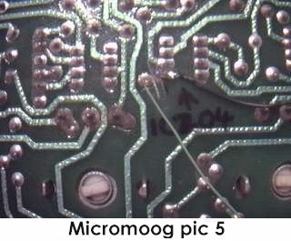
16) The CV connection
must be made next. The original local keyboard voltage buffer is
IC204A. Locate the copper PC board trace which is coming from pin
1 and cut it to break the connection. Solder the MIDIJACK #3 blue
wire to the now-isolated pin 1 on IC204A. This work is seen in Micromoog
pic 5. The connections to components on the board may be made
on the top component side or bottom foil side, whichever is easier,
but the Micromoog has a double-sided PC board of fairly good quality which
has the top side about 95% covered with metal, so it may be safer
to make most of these connections on the bottom foil side to avoid short-circuits
from loose wires.
17) Solder the MIDIJACK #4 white wire to the input of your new glide circuit. Solder a wire jumper from the ouput of your new glide circuit to the copper trace that is now disconnected from IC204A-pin 1, which happens to be one end of 4.7K resistor called R257. It is a good idea to cut little pieces of electrical insulating tape and use them to secure the new jumpers to the board to keep your work neat and prevent the solder joints from breaking while putting it all back together.
18) Moog synthesizers generally do not disconnect the keyboard from the trigger circuit with a switched jack as they should. For this reason, the trigger jacks will still trigger the envelope generator even with the MIDI activated. The MIDIJACK S-trigger wire must then be connnected in parallel with the existing trigger wire. Locate the orange wire which going to the back of the S-trigger jack. Leave it connected as it is and solder the MIDIJACK #7 brown wire to the same terminal on the jack, or somewhere near the other end, which would be at connector P2-pin3.
19) The MIDIJACK #5
yellow wire, #6 green wire, and #8 violet wire (unless it is
used for a special function) may be cut off at this time because they are
not needed for adding MIDI to the Micromoog.
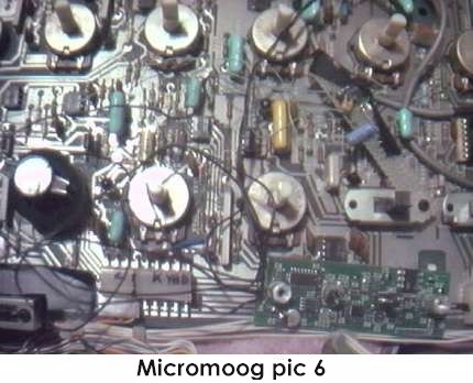
20) Now that all connections
have been made, the Micromoog board should look as shown in Micromoog
pic 6. Notice the small glide circuit mounted diagonally on the
edge of the release switch. It is a good idea to cut short pieces
of electrical insulating tape and use them to secure the MIDIJACK wires
to the inside of the chassis so they will not rattle and break loose inside
the case once the instrument is returned to service. The MIDIJACK
hardware packet contains nylon cable ties which can be used to tie the
MIDIJACK wires to the original Micromoog wire bundles.
15) Carefully examine all soldered connections for possible short circuits before closing the instrument.
16) Close chassis and secure with screws or whatever hardware your new configuration requires.
17) Test and calibrate using the procedures described in the MIDIJACK Quick Installation Manual.
18) It is probably
a good idea not to use the oscillator CV and S-Trigger input jacks while
MIDI is activated or vice versa.
Copyright © 2000 Synhouse
Multimedia Corporation