 |
Moog Source |
|
Moog Source |

The following plans describe a method of adding MIDI capability to the
Moog Source analog synthesizer for $99 with the Synhouse MIDIJACK.
Some drilling is required. There is plenty of space on the Source
to mount the MIDIJACK with the provided hardware. The installation
of the MIDIJACK in a Source is one of the easiest modifications of all.
In fact, with the MIDIJACK, it is possible to convert the Source
to MIDI without even removing a single circuit board from the instrument!
The correct analog I/O signals are easy to find and connect to the MIDIJACK.
Like many older American synthesizers, the Moog Source has panel-mounted
CV/gate jacks with solder lug terminals and the MIDIJACK wires can simply
be soldered right inside the panel and the whole MIDI conversion job can
be done in 30-45 minutes. The 1/4" jacks do not even need to be unscrewed
from the back panel. They may be left in place and soldered right
on the spot. You can do this yourself if you have a little experience
with electronic repair and the soldering of wires and circuit boards.
If not, these plans may assist a professional repair shop installing
the MIDIJACK for you. The particular installation on which this document
is based was on Moog Source serial #2649, other revisions may be
different. It is best to download these notes and photos and print
them out on paper to look at while working on the instrument and make notes
and check off the steps as you go. As with any project, you
should completely read and understand each step of the instructions before
starting. All repairs and modifications made to your instruments
will be done at your own risk and Synhouse Multimedia Corporation assumes
no liability for personal injury caused or damage to equipment or loss
of use caused directly or indirectly by the use of these plans. If
in doubt, don't do it!
Instructions:
1) Be sure to have the correct tools and supplies for for the job. If you do not have them, get them. You will need a regular size Phillips screwdriver, a smaller size Phillips screwdriver, needlenose pliers, wire cutters or other flush cut nippers, a hobby knife such as an X-Acto, scissors, a soldering iron, solder, electrical insulating tape, and a black Sharpie permanent ink marking pen. If you intend to mount the DIN jack on the back panel with the rest of the jacks (highly recommended), it is best to use a chassis punch (a small hand tool that safely cuts a clean hole in a metal panel) to make the hole for the DIN jack, and an electric drill with a 1/8" or similar size drill bit to drill holes for the 4-40 hardware used to mount the DIN jack, and also a 1/4" or 5/16" drill bit to make a pilot hole to start the chassis punch. The correct size for mounting a MIDI DIN jack is 14.5 mm metric or 5/8" SAE (.62"/15.9 mm) in American sizes. A chassis punch may be purchased from any good tool or hardware store. If it is more convenient, a punch may be mail ordered via internet or telephone from Mouser Electronics at http://www.mouser.com or (800) 346-6873. The Mouser part number is 586-3803 for the name-brand Greenlee 730-5/8 (about $30). The cheaper house brand part number is 380-0145 (less than $20). The service from Mouser is unpredictable and the house brand ordered by Synhouse for the test installation took three months to be delivered, while the Greenlee part was delivered in one week. Mouser refused to give even a small discount to customers of Synhouse, so no recommendation is deserved or being made here, and any other source you know of to buy this type of tool is highly recommended and certainly a better place to buy from for all of your needs now and in the future. You will also need an 11 mm wrench (for Greenlee) or 1/2" wrench (for the Mouser house brand punch) or adjustable wrench to turn the chassis punch while cutting the hole. An automatic center punch would also be useful. This is an inexpensive spring-loaded pointed punch that can mark your drilling spot without the use of a hammer. Marking the holes with this small indentation will allow you to drill cleanly without slipping and scratching the synthesizer or drilling through your knee.
2) Fully test the Moog Source to be converted to MIDI. Be sure that all functions such as the envelope generator work and that the instrument plays in tune while playing along with a known well-tuned instrument such as a newer digital synthesizer or sampler keyboard. If it doesn't work properly without MIDI, it certainly won't work with it.
3) Extreme caution should be taken while working on the Moog Source. The unit should be unplugged while open and even then, the power supply may pose some electric shock hazard due to residual voltage in the power supply. Also note that the Moog Source is considerably more complicated than other old monosynths and has many connectors that go from the upper case to the lower case and could become strained or broken if the two halves are pulled too far apart.
4) Remove the six Phillips screws that hold the lower case in place. Four are on the bottom near the corners and two are on the rear panel near the lower edge. Carefully lift the top half of the case and tilt it upright on the back panel so you can see both upper and lower circuit boards from your work position. Be careful not to drop it.
5) Turn the synthesizer
upside down and shake out any dust and debris that may have accumulated
inside the instrument over the years.
6) Determine the place
where the MIDIJACK circuit board will be mounted and test fit the board
into its' correct place inside the case. One place to mount it is
on the front panel to the right of the volume control. The Source
is fairly small and has a lot of circuitry inside, and many places
on the panel that look like a good mounting spot while looking from the
outside actually have circuit boards or blocks of wood on the inside.
You may choose your own mounting location, but be careful to avoid
putting the board or wires near the high voltage transformer and fuse connections
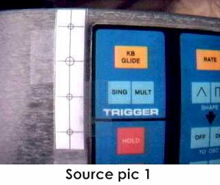
in the rear of the instrument. The MIDIJACK hardware packet has paper
drilling templates for easy installation. Use the paper drilling
template labeled MIDIJACK Board Mounting to properly mark and drill the
holes. The photo called Source pic 1 shows the paper drilling
template in place. Once taped in place, the holes may simply
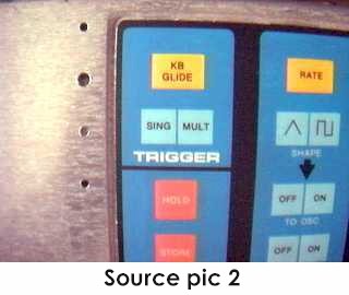
be center-punched and drilled through the paper. The perfect size
drill bit for the switch stem and two screw holes is 9/64", and the
perfect size for the scale adjust trimpot is 3/16". Drill the holes.
The photo called Source pic 2 shows the location of the newly drilled
mounting holes.
7) Temporarily mount
the MIDIJACK board in place. When mounting the MIDIJACK board,
the switch should be fitted so well in the panel that the switch stem will
not wiggle at all once in place. It should not have any free play
but also should not be so tight that it binds. When the switch is
pressed, it should have a definitive "click" and bounce back like
the button on a new VCR. You will never regret spending too much
time on this and good attention to detail will make the perfect MIDIJACK
installation. The hole in the panel that is over the MIDIJACK scale
adjust trimpot should be about 3/16" so a Synhouse Pocket Screwdriver can
fit through the panel for periodic adjustment. Once the fitting is
correct, remove the board. Although the MIDIJACK gets power
to operate from the synthesizer in which it is installed, it has
a very high-quality regulated supply of its own which allows it to operate
with an unregulated input. In the case of the Moog Source,
there may be some digital switching noise or other irregularities present
in the +15v supply. As an extra precaution to help stabilize any
voltage ripple which may become audible in the form of unwanted noise vibrato
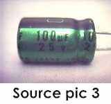
in the CV, two solder pads have been placed on the lower side of
the MIDIJACK board to solder a 100 uF/25v (or greater) radial-lead electrolytic
capacitor in place, upside-down, under the board. The
pads are on the end of the board nearest the header for the wiring harness
and the positive side of the capacitor should go in the square solder pad
marked with a + on the silkscreen. Such a capacitor is seen in Source
pic 3 and is readily available from any electronic supply store,
even Radio Shack with their part number 272-1028. It may not be necessary
to add this capacitor, but it is a good idea. This extra capacitor
may be added in any other MIDIJACK installation as well, but extensive
testing has proven this to be completely unnecessary. Remount the
MIDIJACK board and tighten the screws.
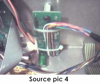 |
The installation of the
board with extra capacitor can be seen in Source pic 4.
The completed MIDI control panel installation is shown in Source pic 5.  |
| 8) Determine the place that the MIDI input DIN jack will be mounted. A good place to mount it is on the back panel between the FINE TUNE knob and the AUDIO OUT jack, as photographed in this example. There is a not a lot of room behind the rear panel of the Source, so you may be limited in your choice for suitable DIN jack mounting locations. The way to make this look like original Moog factory equipment is to mount the DIN jack outside the metal panel (to match the look of the CASSETTE INTERFACE DIN jack if so equipped) instead of inside the panel as in a normal MIDIJACK installation. To do this, mark one of the two wires (#9 orange or #10 gray) at the terminals of the DIN jack with a marking pen or tape to remember the polarity then desolder both wires. Remove the FINE TUNE knob and potentiometer for easier access to the panel, and use the paper drilling template labeled DIN Jack Mounting to properly mark and drill the holes as shown in Source pic 6. | 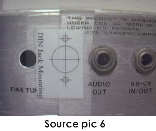 |
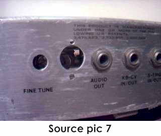 |
It is advisable to use a chassis punch to make the hole for the DIN jack. Remember that the DIN jack is to be mounted with the smaller 4-40 hardware size rather than the larger 6-32 size that secures the main board. Drill two holes for the screws then drill a slightly larger hole in the center to act as a pilot hole for the chassis punch. Use the chassis punch to cut the hole and be sure that the wrench is turning the tool from inside the Source, not outside, so the cutting edge is coming from the outside. This will ensure that the outer edge is perfectly smooth. The properly cut mounting holes may be seen in Source pic 7. |
| The MIDIJACK hardware packet contains both long and short 4-40 screws for the DIN jack. Use the two long ones for installation on a thick aluminum panel such as the Source. When all three holes are perfect, put the DIN jack in place outside the chassis and secure with the two screws from the outside, and the four split washers and two 4-40 nuts on the inside and tighten with a small Phillips screwdriver from the outside and needlenose pliers from the inside. These nuts should be very tight. By using the Synhouse paper drilling template, a center punch to start the drill, and a chassis punch, your Source will look like it had MIDI when it came from the factory, as in Source pic 8. | 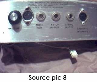 |
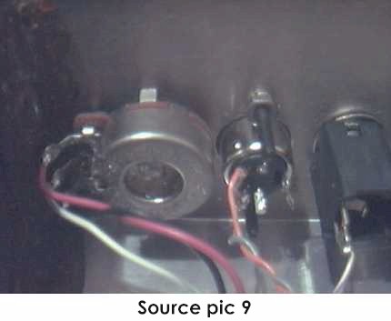 |
Reconnect the wires to the DIN jack at this time. Reinstall the FINE TUNE potentiometer and knob, but rotate the position 180 degrees so that the solder terminals and wires on the potentiometer will be clear of the newly mounted DIN jack. This new arrangement can be seen in Source pic 9. |
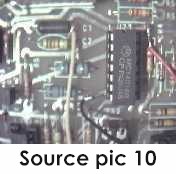
10) The MIDIJACK #1
black and #2 red wires must be soldered in place to get the ground and
power for the MIDIJACK. Locate IC U23 near the rear center of the
analog board. Resistor R57 is just to the right of it. Solder
the MIDIJACK #1 black wire to the circuit board trace connected to U23
pin 7, the ground pin of the chip. This PCB trace is at the
lower left of the chip and goes to the left, and can be seen in Source
pic 10. Solder the MIDIJACK #2 red wire to the lead of R57 which
is nearest the rear of the instrument, the end of the resistor which
goes to U23 pin 14, the +15v power pin of the chip. Make these
connections very carefully. Please note that the beige wire further
to the left of IC U23 is not related to the MIDIJACK, it is a Moog
factory-installed jumper wire used to correct a factory defect in the design
of the Moog Source photographed here and should not be touched.
11) Locate the factory
Moog wire which is white with black and brown stripes and is soldered to
the back of the KB-CV IN/OUT jack. This wire connects to the ring
of the KB-CV IN/OUT jack. Remove the wire from the solder terminal
by desoldering it. Solder the MIDIJACK #3 blue wire to the now-empty
isolated CV terminal.
12) Solder the MIDIJACK #4 white wire to the now-disconnected factory Moog wire which is white with black and brown stripes. Carefully wrap the solder joint with electrical insulating tape.
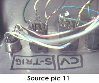
13) Moog synthesizers
generally do not disconnect the keyboard from the trigger circuit with
a switched jack as they should. For this reason, the local
keyboard will still trigger the envelope generator even with the MIDI activated.
The MIDIJACK #7 brown wire (S-trigger wire) must then be connnected in
parallel with the existing trigger wire. A small signal diode can
be inserted to isolate the signal so the local keyboard will still work
when the MIDI is turned off. The correct type of diode is included
with the MIDIJACK in the accessory packet, but may also be purchased
locally at any electronics store such as Radio Shack as a 1N914 or 1N4148
or equivalent type of switching diode. Locate the factory Moog wire
which is white with violet stripes and is soldered to the back of the S-TRIG
IN/OUT jack. This wire connects to the tip of the S-TRIG IN/OUT jack.
Leave it connected as it is and solder the anode end of the diode (the
end AWAY from the little black band) to this point and solder the MIDIJACK
#7 brown wire to the cathode end of the diode (the end with the little
black band). In summary, the MIDIJACK #7 brown wire goes to
the band end of the diode, the other end of the diode goes to the
same terminal on the trigger jack that still has the white wire with violet
stripes soldered to it. There will now be a factory wire AND a diode
connected to this terminal of the jack. The finished connections
can be seen in Source pic 11. Please note that this connection
is correct but is different from other Moog installations described in
the MIDIJACK Quick Installation Manual.
14) The MIDIJACK #5
yellow wire, #6 green wire, and #8 violet wire (unless it is
used for a special function as described in the Advanced Installation Manual)
are not required for for adding MIDI to the Moog Source, but it is
a good idea not to permanently cut these wires off, as an alternate
installation method may become useful later. It is best to wrap the
ends of these unused wires with electrical insulating tape and bundle them
with the other wires when finishing the installation.
15) The MIDIJACK hardware packet contains nylon cable ties which should be used to tie the MIDIJACK wires into little bundles and to attach them to the factory wires inside the Source now that all connections have been made. This will secure the MIDIJACK wires so they will not rattle and break loose inside the case once the instrument is returned to service.
16) Carefully examine all soldered connections for possible short circuits before closing the instrument.
17) Close the instrument and replace the six Phillips screws that hold the upper and lower halves of the case together. Four are on the bottom near the corners and two are on the rear panel near the lower edge.
18) Test and calibrate using the procedures described in the MIDIJACK Quick Installation Manual.
19) This installation can be completed in 30-45 minutes.
With the MIDIJACK, the Moog Source is perfect for computer-controlled live performances with real-time hands-on sound editing capabilities. The envelopes may be adjusted on the fly, the resonant filter dramatically swept with a fast spin of the incremental encoder, and the pitch and mod wheels work as always. The Moog Source is quite a bit different than other analog monosynths and the MIDI control that results from putting a MIDIJACK on it is different as well. The lowest note on the Source keyboard is C, and when you send a MIDI C to it via the MIDIJACK, it plays a C on the Source. As always, the MIDIJACK can be put into MIDI on or MIDI off modes, but when using MIDI to control the Source, the local keyboard may be played as well, even while it is in MIDI on mode, just like with any factory MIDI keyboard. In this installation, the keyboard voltage and the MIDIJACK voltage are combined to affect each other but the envelope triggering still work independently but simultaneously. Additionally, the local keyboard may be used to transpose the incoming MIDI notes, and it works very well and with good pitch stability because the Moog Source has an unusual digital keyboard circuit which will not suffer from old-fashioned sample and hold droop. The user can select either mode at any time, but may prefer to leave it in MIDI on mode all the time.
If you power-up the Moog Source with MIDI on mode previously enabled,
you may not be able to hear sound while playing the local keyboard.
After playing something via MIDI, you will be able to play the local
keyboard and hear sound. Why? This is not a failure to trigger,
but rather combining the very high MIDIJACK top MIDI note 127 control voltage
with the local keyboard voltage which is always fairly low due to the limited
factory range of the small keyboard on the Moog Source. The combination
of those two voltages is a voltage that may still be too high to hear because
the fundamental frequency of the note produced may be higher that the cutoff
frequency of the lowpass filter. To hear a demonstration of this,
turn up the pink noise source and continue to play the keyboard.
You will now be able to hear each note playing even if the VCO pitch is
too high. You can send a lower MIDI note at this time to lower the
combined voltage and bring the range back down closer to where you expected
it. This power-up status is due to the MIDIJACK Analog Calibration
Mode. When any MIDIJACK-equipped synthesizer is powered-up with MIDI
On Mode previously selected before last power-down, the on-board
computer causes it to automatically and silently go into the Analog Calibration
Mode where the MIDIJACK #4 white wire (MIDIJACK CV output) puts out the
correct voltage of the highest MIDI note, MIDI note 127, which
is +10.58 volts. This can be adjusted with the scale adjustment trimmer.
This note will not be heard at the audio output of the synthesizer because
the gate is not active during Analog Calibration Mode. You can read
more about this mode in the MIDIJACK Quick Installation Manual. If
an analog synthesizer has the built-in glide function factory wired to
be pre-CV/gate jacks, it will not have use of the built-in glide
with external CV/gate control. The installation of a MIDIJACK is
no different than using external CV/gate control, having no access
to the built-in glide. If glide is required for MIDI use, an
easy solution for real analog glide is provided in the Advanced Installation
Manual, but is beyond the scope of these simple instructions.
Copyright © 2000 Synhouse
Multimedia Corporation