
Moog MicroMoog
|
Moog MicroMoog |
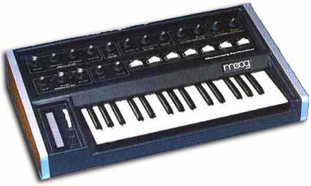 The following plans describe a method of adding MIDI capability to the Moog Micromoog analog synthesizer with the Synhouse Moogiestyle MIDIJACK. This will allow the Moog Micromoog to be used as a MIDI analog monosynth. Some drilling is required. The micro size and black color of the MIDI button are such a perfect match for the Micromoog that it makes it look as if it came from the factory with the MIDI interface. The installation of the MIDIJACK in a Micromoog is one of the easiest modifications of all. In fact, with the MIDIJACK, it is possible to convert the Micromoog to MIDI without even removing a single circuit board from the instrument! The correct analog I/O signals are easy to find and connect to the MIDIJACK. Like many older American synthesizers, the Moog Micromoog has panel-mounted CV/gate jacks with solder lug terminals and the MIDIJACK wires can simply be soldered right inside the panel and the whole MIDI conversion job can be done in one hour. The 1/4" jacks do not even need to be unscrewed from the back panel. They may be left in place and soldered right on the spot. This modification reroutes the local keyboard signals through the computer-controlled analog switching matrix of the MIDIJACK by extracting the signal and inserting the users' choice of local keyboard control or MIDI. You can do this yourself if you have a little experience with electronic repair and the soldering of wires and circuit boards. If not, it is recommended that you send the instrument to Synhouse L.A. for a quick, low-cost Factory Installation. It is best to download these notes and photos and print them out on paper to look at while working on the instrument and make notes and check off the steps as you go. As with any project, you should completely read and understand each step of the instructions before starting. All repairs and modifications made to your instruments will be done at your own risk and Synhouse Multimedia Corporation assumes no liability for personal injury caused or damage to equipment or loss of use caused directly or indirectly by the use of these plans. If in doubt, don't do it! Instructions: 1) Be sure to have the correct tools and supplies for for the
job. If you do not have them, get them. You will need
a regular size Phillips screwdriver, a smaller size Phillips screwdriver,
needlenose pliers, wire cutters or other flush cut nippers,
a hobby knife such as an X-Acto, scissors, a soldering iron,
solder, electrical insulating tape, and a black Sharpie permanent
ink marking pen. If you intend to mount the DIN jack on the back
panel with the rest of the inputs (highly recommended), you will
need to use a chassis punch (a small hand tool that safely cuts a clean
hole in a metal panel) to make the hole for the DIN jack, and an
electric drill with a 3/32" or similar size drill bit to drill holes for
the 4-40 hardware used to mount the DIN jack, and also a 1/4" or
5/16" drill bit to make a pilot hole to start the chassis punch.
The correct size for mounting a MIDI DIN jack is 14.5 mm metric or 5/8"
SAE (.62"/15.9 mm) in American sizes. A chassis punch may be purchased
from any good tool or hardware store. If it is more convenient,
a punch may be mail ordered via internet or telephone from Mouser Electronics
at http://www.mouser.com or (800) 346-6873.
The Mouser part number is 586-3803 for the name-brand Greenlee 730-5/8
(about $30). The cheaper house brand part number is 380-0145 (less
than $20). The service from Mouser is
2) Fully test the Moog Micromoog to be converted to MIDI. Be sure that all functions such as the envelope generator work and that the instrument plays in tune while playing along with a known well-tuned instrument such as a newer digital synthesizer or sampler keyboard. If it doesn't work properly without MIDI, it certainly won't work with it. 3) Extreme caution should be taken while working on the Moog Micromoog. The unit should be unplugged while open and even then, the power supply may pose some electric shock hazard due to residual voltage in the power supply. 4) Open the case and turn the synthesizer upside down and shake out any dust and debris that may have accumulated inside the instrument over the years. 5) Determine the place where the MIDIJACK circuit board will be
mounted and test fit the board into its correct place inside the
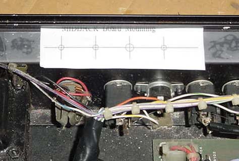 The perfect size drill bit for the switch stem and two screw holes is
9/64", and the perfect size for the scale adjust trimpot is 3/16".
Drill the holes. A photo called MM-pic2 shows the location of the
newly cut mounting holes:
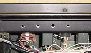 6) Mount the MIDIJACK board in place. When mounting the MIDIJACK board, the switch should be fitted so well in the panel that the switch stem will not wiggle at all once in place. It should not have any free play but also should not be so tight that it binds. When the switch is pressed, it should have a definitive "click" and bounce back like the button on a new VCR. You will never regret spending too much time on this and good attention to detail will make the perfect MIDIJACK installation. The hole in the panel that is over the MIDIJACK scale adjust trimpot should be large enough so a Synhouse Pocket Screwdriver can fit through the panel for periodic adjustment. 7) Determine the place that the MIDI input DIN jack will be mounted.
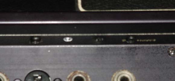
One place is on the rear jackpanel 1" below the audio and modulation input
jacks. The way to make this look like original Moog factory equipment
is to mount the DIN jack inside the metal panel after marking the bare
metal edges of the hole with a black Sharpie permanent ink marking pen
to match the black finish of the original metal chassis. Use the
paper template to mark the correct spots to drill and cut as shown in MM-pic3:
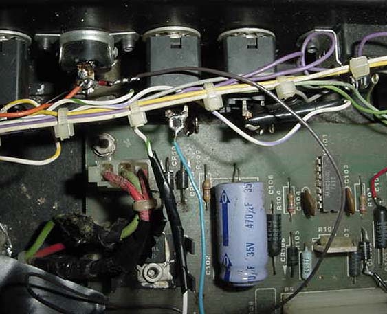
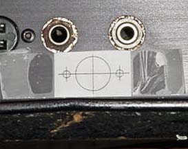 It is advisable to use a chassis punch to make the hole for the DIN jack. Remember that the DIN jack is to be mounted with the smaller 4-40 hardware size rather than the larger 6-32 size that secures the main board. Drill two holes for the screws then drill a slightly larger hole in the center to act as a pilot hole for the chassis punch. Use the chassis punch to cut the hole and be sure that the wrench is turning the tool from inside the Micromoog, not outside, so the cutting edge is coming from the outside. This will ensure that the outer edge is perfectly smooth. If you do it this way, you may need to temporarily unscrew the keyboard and use a long socket extension to be able to turn the punch tool, as it is so close to the base. The properly cut mounting holes may be seen in MM-pic4: 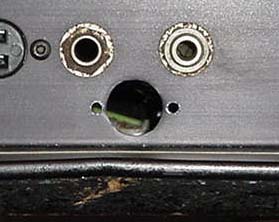 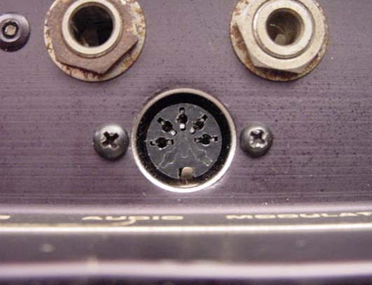  The MIDIJACK #1 black wire must be soldered to the anode end of the
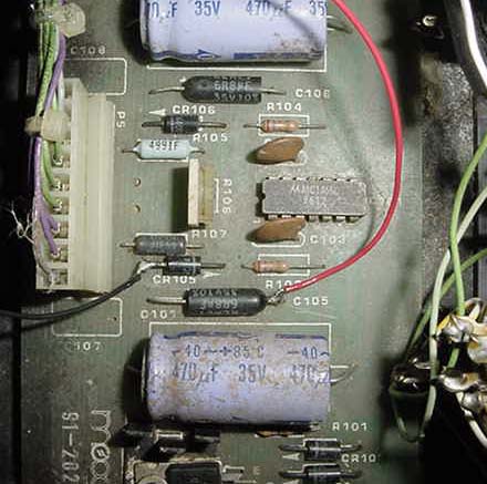
diode CR105 (the end AWAY from the little band painted on it) to get the
ground for the MIDIJACK. The MIDIJACK #2 red wire must be soldered
to the positive side of capacitor C105 to get the power for the MIDIJACK.
These connections may be seen clearly in the closeup photo MM-pic7:
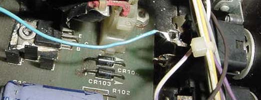
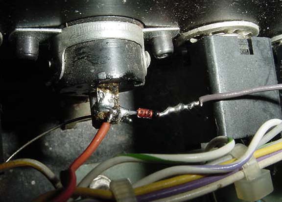
 9) The CV connection must be made next. Locate the CV input
jack labeled OSC. At the rear of the jack, the top terminal
has a wire soldered to it which is white with green stripes. Desolder
this wire. Solder the MIDIJACK #3 blue wire to empty terminal as
seen in MM-pic8:
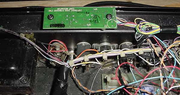
   12) Now that all connections have been made, the MIDIJACK
board, DIN jack, and all connections should look as shown in
MM-pic11:
  packet contains nylon cable ties which can be used to tie the MIDIJACK wires to the original Micromoog wire bundles. 14) Carefully examine all soldered connections for possible short circuits before closing the instrument. 15) Close chassis and replace the screws. 16) Test and calibrate using the procedures described in the Moogiestyle MIDIJACK Quick Installation Manual. For calibrating the MIDIJACK on a Micromoog, please read question 6 from the Analog User Answer Forum page: Question 6: I have a MIDIJACK MIDI interface installed in my Micromoog and it never plays in tune. The intonation of the keyboard is always bad. What's wrong? Answer: The Micromoog never played in tune with anything except its' own keyboard. Controlling externally via CV/gate jacks always caused the notes to be out of tune whether it was 25 years ago from a Minimoog or more recently with some sort of MIDI controller type of device. It has been said to be not 1 volt per octave, but rather about .9 volts per octave due to some design error. This is no longer a problem. Do not underestimate the versatility of the MIDIJACK. It is all hardware. If your Micromoog has the problem of being .9v/octave instead of 1v/octave, it can be corrected with a quick adjustment on the MIDIJACK. Play a few notes on the Micromoog through MIDI. If the notes are all sharp as you go up, like the whole keyboard has steps that are too far apart, then it is less than 1v/octave. The solution: The MIDIJACK has a scale adjustment trimmer that affects the musical intonation of the analog synthesizer while it is under MIDI control. It is less than one inch away from the MIDI function button and may be adjusted by inserting a small flatblade screwdriver into the control panel opening. A Synhouse Pocket Screwdriver fits perfectly. The scale adjustment trimmer may be set by ear if the Analog User has a good sense of pitch. A MIDI controller keyboard should be connected with a MIDI cable to the MIDIJACK and the audio output of the Micromoog to a sound system for monitoring. The MIDIJACK should be in MIDI On Mode and set to the same MIDI channel as the MIDI controller keyboard. While playing alternating notes on the MIDI controller keyboard that are an octave apart, the user can turn the scale adjustment trimmer very slowly until the proper one-octave interval is heard and the entire keyboard plays in tune. It may be easiest to hear the tones clearly by adjusting the Micromoog so that the filter is open with the frequency set to maximum, the emphasis set to minimum, and the envelope generators set to sustain, without any vibrato on the oscillators. An extra help would be to use a MIDI synthesizer or sample playback keyboard as the MIDI controller and listen to its sound output as a reference tone to match the Micromoogs' intonation while adjustments are being made. A low note may be played on the MIDI keyboard while the Micromoogs' master tuning knob is adjusted to bring the two sound sources into tune. Next, play higher octave intervals of that note, and slowly turn the MIDIJACK scale adjustment trimmer until the entire keyboard plays in tune. For the Micromoog to work properly, the trimmer will have to be turned about 10% down, or counterclockwise, from the Synhouse factory 1v/octave setting. With this altered setting, the MIDIJACK should be putting out MIDI notes 0-127 at a scaling interval of .9v/octave. You can shrink or stretch your scaling from 0v/octave (not too musical) to approximately 1.2v/octave. Actually more than that, you could turn it all the way up to 2v/octave but the MIDI notes above 64 would be clipped and all the same pitch. The MIDIJACK is designed this way because most old synthesizers are out of calibration in one way or another and this is one way to try to bring them back into adjustment. Additionally, it allows the MIDIJACK to work in instruments that have exponential oscillators other than 1v/octave, such as EML (Electrocomp 101 and others) and EMS (Synthi AKS and VCS-3). Analog calibration should only be performed occasionally, as overuse of the scale adjustment trimmer may cause excessive wear and premature failure of the part. 17) It is probably a good idea not to use the Micromoog built-in local keyboard or oscillator CV and S-Trigger input jacks while MIDI is activated or vice versa. 18) This installation can be completed
in approximately one hour, depending on how you mount the MIDIJACK
board.
Copyright © 10/07/2002 Synhouse Multimedia Corporation |