 |
Korg MS-20 |
Do It Yourself Special:
Updated for 2010!
(click here to go directly to the update)

The following
plans describe a general method of adding MIDI capability to the Korg MS-20
analog synthesizer with the Synhouse Original
MIDIJACK.
Later on, a specific method to install the Synhouse
MIDIJACK II: Hertz
so good! will be briefly described.
You can do this yourself
if you have a little experience with electronic repair and the soldering
of wires and circuit boards. If not, it is recommended that
you send the instrument to Synhouse L.A. for a quick, low-cost Factory
Installation. All repairs and modifications made to your instruments
will be done at your own risk and Synhouse Multimedia Corporation assumes
no liability for personal injury caused or damage to equipment or loss
of use caused directly or indirectly by the use of these plans. If
in doubt, don't do it!
Instructions for installing the Original
MIDIJACK:
1) Proceed with the installation
as described for the Korg
MS-10
but make the appropriate changes as they relate to the Korg MS-20. The
three manuals supplied with the MIDIJACK will provide all necessary
information, as they relate to any synthesizer.
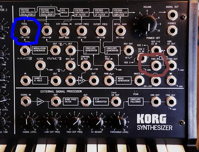
2) For the MIDIJACK #3 blue wire and MIDIJACK #4 white wire, connect to the jack circled in blue, and the MIDIJACK #7 brown wire to the jack circled in brown in this photo:
4)
With the Original MIDIJACK,
the Korg MS-20 is perfect for computer-controlled live performances
with
real-time hands-on sound tweaking and patching. The Korg MS-20 is
quite a bit different than other analog monosynths and the MIDI control
that results from putting an Original MIDIJACK on it is different as
well. The Original MIDIJACK is using the Korg's built-in
linear-to-exponential
converter to get the correct VCO control. To start playing MIDI, you
must let the instrument warm up then momentarily press down one note
on the Korg keyboard to provide the correct offset voltage. The
keyboard
intonation can be adjusted with the knob in the FREQUENCY MODULATION
section
labeled MG/T.EXT. The correct setting will probably be fairly high,
between 8 and 10. If the Korg TOTAL input is warmed up and
working
correctly, the Original MIDIJACK will play MIDI notes perfectly
in
tune. An advanced user may find it useful to add an extra fine
tune
trimming potentiometer in series with the MG/T.EXT knob to get finer
control
and make quick adjustments when temperature changes cause drift. The
MS-20 keyboard can be used to transpose the incoming MIDI notes on
the fly.
Instructions for installing the MIDIJACK
II: Hertz so good!:
(see 2010 update with easy diagram in red below)
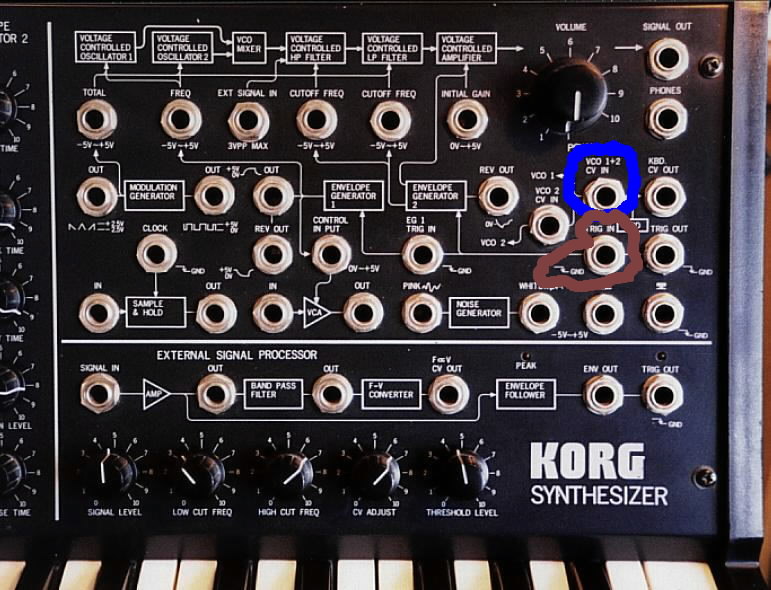
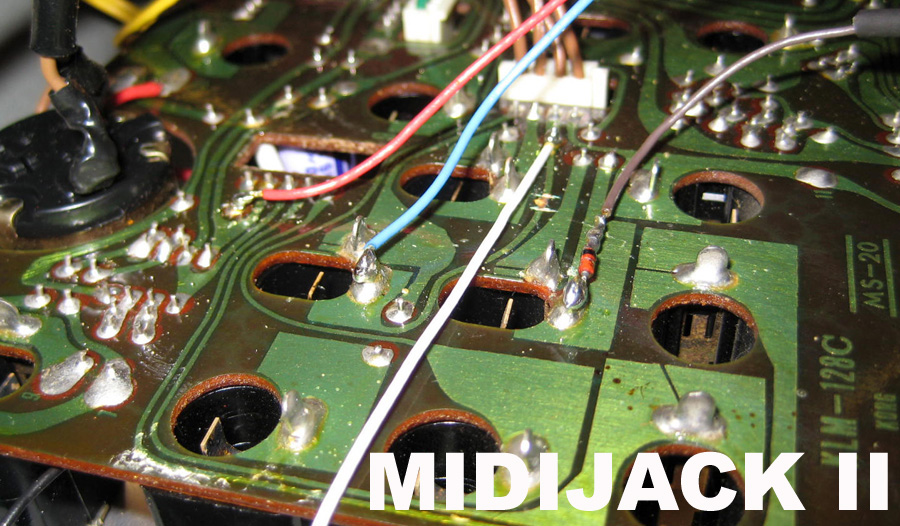
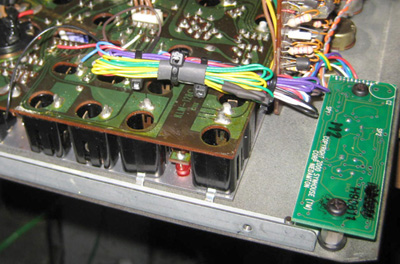
1) The method of installation for the MIDIJACK II: Hertz so good! is exactly the same for everything except the connections for the MIDIJACK #3 blue wire and MIDIJACK #4 white wire. Instead of being connected to the volt/octave input, connect these in the same manner to the regular Hz/volt VCO input jack. The pros and cons of using the Original MIDIJACK vs. the MIDIJACK II: Hertz so good! are discussed in question 39 on the Analog User FAQ's page. The MIDIJACK board may be mounted in the lower right corner of the panel as seen here:

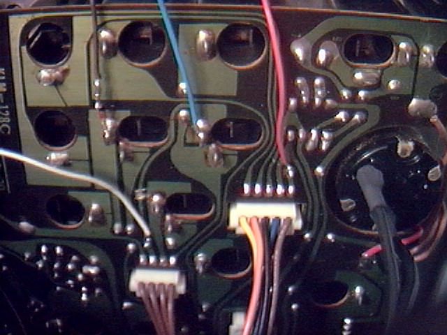
The MIDIJACK #2 red wire can be seen soldered to the trace next to the brown Korg wire above.
The MIDIJACK #3 blue wire is soldered to the solder terminal coming through the board from the back of the jack labeled VCO 1+2 CV IN as shown above. The trace coming from that must be cut to break the signal as shown above.
The MIDIJACK #4 white wire must be soldered to the other side of the break in that trace, as shown above, where it was most convenient to solder onto the lead of a component coming through the board and trace.
The MIDIJACK #5 yellow and the MIDIJACK #6 green wires are not used in the installation and may be taped up.
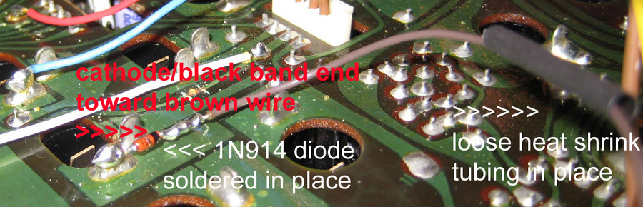
The MIDIJACK #7 brown wire must be connected next. The Korg MS synthesizers use an inverted gate signal similar to Moog synthesizers and the MIDIJACK #7 brown wire (S-trigger wire) works well for this. The MIDIJACK #7 brown wire (S-trigger wire) must then be connected in parallel with the existing trigger circuit. A small signal diode can be inserted to isolate the signal so the local keyboard will still work when the MIDI is turned off. The correct type of diode is included with the MIDIJACK in the accessory packet, but may also be purchased locally at any electronics store such as Radio Shack as a 1N914 or 1N4148 or equivalent type of switching diode. Locate the factory Korg terminal which connects to the tip of the TRIG IN jack, which is shown in the photo above. This terminal connects to the tip of a plug inserted in the the TRIG IN jack. Solder the anode end of the diode (the end AWAY from the little black band) to this terminal and solder the MIDIJACK #7 brown wire to the cathode end of the diode (the end with the little black band). In summary, the MIDIJACK #7 brown wire goes to the band end of the diode, the other end of the diode goes to the terminal on the trigger jack. The finished connection with the diode can be seen in the photo above.
4) If this installation method is
not immediately and completely clear to you, you should refer the
installation to Synhouse for Factory
Installation.
If an analog synthesizer has the built-in
glide function factory wired to be pre-CV/gate jacks, it will not
have use of the built-in glide with external CV/gate control. The
installation of a MIDIJACK is no different than using external CV/gate
control, having no access to the built-in glide. If glide is
required for MIDI use, an easy solution for real analog glide is
provided in the Advanced Installation Manual, but is beyond the scope
of these simple instructions.
At this time, the MIDIJACK II is considered to be the far better choice for the MS-20, as it is designed especially for the Hz/v system used by the MS-20 and leaves more synth resources available.
New photos were taken during an installation in 2010. For those installing the MIDIJACK II into the MS-20, these
photos (posted below) will give a more direct, quicker
understanding of this relatively simple task than the previous
instructions (above) that required a reading and understanding of the
MS-10 installation, then understanding how the MS-20 is slightly
different, then referring to the general manuals, etc.. This shows all
connections that must be made in this installation, shows them all in a
single
view, and shows how all of this work is done in a tiny area of a single
MS-20 circuit board that is only 4" x 6". To make this even easier, the
instructions are noted directly on the photos themselves, and multiple
views are given to be sure of what you are seeing.
When you dismantle the MS-20, use a lot of care and follow the instructions above, but note that there are 18 screws to remove when taking it apart
(not including the ground strap screw/washer/nut). There are seven
screwed through the right side plastic, seven screwed through the left
side plastic, and four along the lower edge in the rear. Be sure notto
remove more than 18 screws, or else things will fall apart and more
reassembly will be required than necessary. For example, don't remove
all the screws from from the underside (just the one forthe ground
strap, after undoing the others), and don't remove the two extra screws
screwed through the left side plastic
nearest the pitch wheel, those hold the pitch wheel assembly in place,
and this quick installation doesn't require any access to that.
Please use a lot of care in your soldering and trace cutting. Although the MS-20 isn't quite as poorly made as the Roland MC-202,
which is the absolute gold standard in garbage synth construction, it
still has some major components made of embarrassingly low grade, low
quality materials. Unlike Roland, at least the Korg MS-20 is in a box
that is half metal and has good quality pots, but the MS-20 PC
boards are of a quality grade that is about a thousand
steps below the quality of the Synhouse MIDIJACK circuit board. Instead
of being made of FR4 epoxy impregnated 94V flameproof fiberglass as
anything from any decent company is, the PC boards that Korg used in
the MS-20 (and no doubt hundreds of other products) are
made of paper phenolic. PC boards made out of this material are about
as durable as stale saltine crackers. This is a grade of material so
low that it is doubtful that a
reputable PC board vendor in the United States could even supply it. In
the MS-20, these are worse than most, being more like syrup-varnished
graham crackers. The whole thing is covered in some gloppy varnish
(perhaps some sticky, feeble attempt at soldermasking), and is not
defluxed at all, so there are little dots and spots of gloppy
varnish and solder flux all over it. Use a lot of care when making
trace cuts and solder joints, and try to use as little heat as
possible, because this crap delaminates and curls up in an instant.
This photo shows the board after the PCB trace has been cut and all the connections have been made:
(The MIDIJACK #1 black wire isn't
fully shown, but you can see 2cm of it in the lower left of the photo.
You can see how it goes under the board and solders to an unused ground
tab on one of the 1/4" jacks. Any one is fine, they are all grounded.)
This
photo shows the board after the PCB trace has been cut and all the
connections have been made. This time, from a slightly different angle,
with notes:
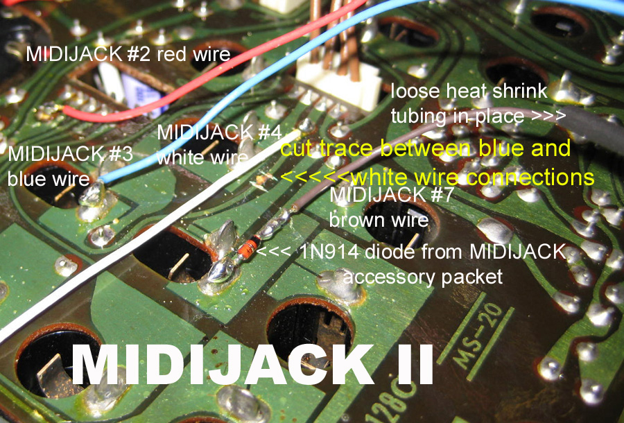
The notes in the photo above are nearly the complete instructions for this installation.
This photo shows the placement of the diode, with notes:
This photo shows the heat shrink tubing placed over the diode to insulate it from touching other metal parts:
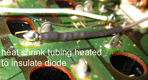
The original instructions said to
use electrical tape for this purpose, which is still okay, but use heat
shrink tubing and a heat gun instead if you have it, as it will never
fall off or become gooey and sticky.
This photo shows the finished
job, with the unused wires insulated and everything tied neatly into
place with the nylon cable ties:
Except for the DIN jack for
MIDI input, the entire installation takes up less than 4" x 6", and, if
done this way, can be done without removing any circuit boards from the
synth. This saves a lot of time. The DIN jack can go anywhere, but the
lower rear right opposite the AC cord is still the best place to put it.
Possibilities for customization:
An alternate method of installation that would in the style of the fully patchable Korg MS-series would be to install the MIDIJACK circuit board inside the synth as intended to get the power for the MIDIJACK from the synths' internal power supply, but solder the MIDIJACK CV output wire (MIDIJACK #4 white wire) and S-Trigger output wire (MIDIJACK #7 brown wire) to a pair of new 1/4" jacks on the panel with the rest of the jacks: